ProForm C500 Treadmill English Manual - Page 8
Be Damaged When The Power Is Turned On. - console
 |
View all ProForm C500 Treadmill manuals
Add to My Manuals
Save this manual to your list of manuals |
Page 8 highlights
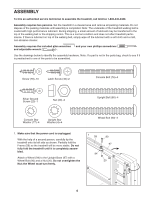
5. Hold the pulse bar bottom against the Pulse Bar Top (71). Make sure that the indicated box inside of the Pulse Bar Top is inserted into a cavity in the pulse bar bottom. Attach the pulse bar bottom with eight Screws (78). Tighten the Screws indicated by the arrows first, and tighten the center Screws last. Be careful not to overtighten the Screws or to pinch any wires. Next, identify the Right Top Endcap (75) and the Left Top Endcap (81) by looking at the slots in the Top Endcaps. Insert the Wire Harness (74) through the slot in the Right Top Endcap, and press the Right Top Endcap into the Right Upright (95). Insert the pulse wire through the slot in the Left Top Endcap, and press the Left Top Endcap into the Left Upright (92). Make sure that the Top Endcaps are oriented exactly as shown. 5 74 Box 75 Pulse Wire 71 81 78 95 78 Pulse Bar Bottom 78 92 6. See drawing 6c. With the help of a second person, hold the Console Base (101) near the Uprights (92, 95). Look under the Console Base and locate the wires on the sides of the Console Base. Make sure that the wires are not routed through the openings for the Trays (67, 39). Drawing 6a shows the correct route for the wires. Drawing 6b shows an incorrect route. Locate the Wire Harness (74) in the Right Upright (95) and the pulse wire in the Left Upright (92). Connect the Wire Harness and the pulse wire to the connectors on the sides of the Console Base (101). Make sure to connect the connectors properly (see the inset drawings). The connectors should slide together easily and snap into place. If the connectors do not slide together easily and snap into place, turn one connector and try again to insert it. IF THE CONNECTORS ARE NOT CONNECTED PROPERLY, THE CONSOLE MAY BE DAMAGED WHEN THE POWER IS TURNED ON. Insert the excess Wire Harness and pulse wire up into the Console Base. 6a 6b Correct 6c 39 Incorrect 67 101 74 95 92 Pulse 74 Wire 7. Set the Console Base (101) on the Left and Right Uprights (92, 95). Thread the four Console Bolts (76) with four Console Star Washers (77) into the Uprights and the Console Base. Be careful not to pinch the wires (not shown) in the Uprights. Tighten the two Console Bolts indicated by the arrows first; then, tighten the remaining two Console Bolts. Make sure that the Left and Right Trays (67, 39) are pressed into the Console Base (101). 8 7 101 39 77 95 76 92 67 77 76 77
-
 1
1 -
2
-
 3
3 -
 4
4 -
 5
5 -
 6
6 -
 7
7 -
 8
8 -
 9
9 -
 10
10 -
 11
11 -
 12
12 -
 13
13 -
14
-
15
-
16
-
17
-
18
-
19
-
20
-
21
-
22
-
23
-
24
-
25
-
26
-
27
-
28
-
29
-
30
 |
 |
