ProForm Edge 2001 Owners Manual - Page 6
resistance
 |
View all ProForm Edge 2001 manuals
Add to My Manuals
Save this manual to your list of manuals |
Page 6 highlights
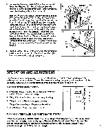
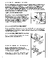
CHANGING THE WEIGHT SETTING OF THE SYSTEM The weight can be changed from a minimum of 30 Ibs, to a maximum of 250 Ibs, in increments of 1 lb. To increase the weight, press the weight increase button. To decrease the weight, press the weight decrease button. The buttons can be held down to change the weight quickly. IMPORTANT: To prevent damage to the system, do not put any tension on the system while changing the weight. Do not push on the press arm or leg lever. If the lat bar is attached to the system, it may be helpful to support the weight of the lat bar with one hand. The system motor will emit a sound to alert you while the weight is being changed. ADJUSTING THE STEPPER RESISTANCE The resistance of the stepper can be changed by moving the cylinder brackets to different holes in the stepper pedals. There are five different resistance levels. To change the resistance, first remove the knobs from the cylinder brackets. Move the cylinder brackets to the desired holes in the pedals, and re-attach the knobs. WARNING: The resistance cylinders may become hot during use. Allow the cylinders to cool before touching them. Slow Fast ATTACHING AND REMOVING THE SEAT SUPPORT The seat support should be attached as described in the assembly instructions. For certain exercises, the seat support must be removed from the system. First, remove the lower cable from the leg lever. The seat support can then be removed by lifting the seat support until the bracket on the seat support is free of the pins on the frame. ATTACHING THE LEG LEVER TO THE WEIGHT SYSTEM To attach the leg lever to the weight system, attach the lower cable to the leg lever using a connector link. ATTACHING THE LAT BAR TO THE WEIGHT SYSTEM To attach the lat bar directly to the lower cable, first disconnect the cable from the leg lift. Remove the seat support from the frame as described above. Attach the lat bar to the cable using a connector link. If desired, the chain can be attached between the lat bar and the cable, using a connector link on both ends of the chain. 6
-
 1
1 -
 2
2 -
 3
3 -
 4
4 -
 5
5 -
 6
6 -
 7
7 -
 8
8 -
 9
9 -
 10
10 -
 11
11 -
 12
12
 |
 |
