ProForm Edge 2001 Owners Manual - Page 7
Maintenance, Trouble, Shooting
 |
View all ProForm Edge 2001 manuals
Add to My Manuals
Save this manual to your list of manuals |
Page 7 highlights
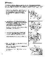
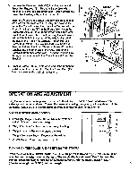
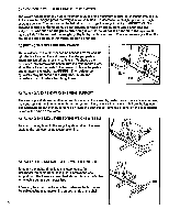
To use the lat bar with the upper cable, the chain must be attached between the lat bar and the cable using the two connector links. The chain can be shortened by attaching the 4 connector links closer together along the chain. IMPORTANT: The proper length of chain between the lat bar and upper cable should be determined by the exercise to be per- formed. Adjust the length of chain until the lat bar is in a comfortable starting position. OPERATING AND "PARKING" THE PRESS ARM The press arm can be put in the operating position as described in the assembly instructions. For certain exercises, the press arm must be set out of the way, or "parked." To "park" the press arm, remove the pull pin and lift the press arm away from the press arm bracket. Insert the pull pin in the upper hole of the press arm bracket and rest the press arm on top of the pull pin. IMPORTANT: When the press arm is in the "parked" position, do not put weight on the press arm or it will be damaged. KO\ ATTACHING AND REMOVING THE VKR The VKR should be attached as described in the assembly instructions. To remove the VKR, lift the bracket on the VKR off of the post on the frame. MAINTENANCE AND TROUBLE-SHOOTING This system is designed to be virtually maintenance-free. Check the system regularly to be sure that all parts are tightened securely. Replace any worn parts immediately. The outside of the system can be cleaned using a damp cloth and mild, non-abrasive detergent. Do not use solvents. ADJUSTING THE WEIGHT SYSTEM If there is slack in the weight system before the weight engages, the cables may need to be adjusted. To adjust the cables, a phillips screwdriver and two adjustable wrenches Lower Cable (not included) are required. Remove the four screws from the right side shield, and carefully move the side shield out of the way. Locate the "L"-shaped bracket with the four holes. The a lower pulley cable will be bolted to the bracket. Remove the bolt and nut attaching the cable to the bracket. Move the cable to the next lower hole in the bracket, and re-attach the "L" Bracket cable with the bolt and nut. Test the weight system before re- attaching the side shield. If the motor stalls or hesitates, the cable is too tight. Move the cable to the next higher hole. If there is still slack in the cables, move the cable to the next lower hole as described above. If the cable is attached to the lowest hole in the bracket and there is still slack in the cables, the cables should be replaced (refer to the back cover). Re-attach the side shield.
-
 1
1 -
 2
2 -
 3
3 -
 4
4 -
 5
5 -
 6
6 -
 7
7 -
 8
8 -
 9
9 -
 10
10 -
 11
11 -
 12
12
 |
 |
