ProForm Strideselect 875 Elliptical English Manual - Page 8
Attach two Pedal Posts 16 to the Left Pedal Arm 14
 |
View all ProForm Strideselect 875 Elliptical manuals
Add to My Manuals
Save this manual to your list of manuals |
Page 8 highlights
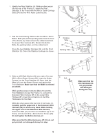
7. Slide the Right Crank Arm (38) onto the four indicated welded bolts; make sure that the Right Crank Arm is in the indicated cutout in the Pedal Disk (8). Next, finger tighten four M8 Jamnuts (80) onto the welded bolts. Then, fully tighten one of the Jamnuts, and then tighten the Jamnut farthest from the first Jamnut. Then, tighten the remaining two Jamnuts. Attach a Hub Cover (48) to the Right Crank Arm (38) with four Cover Screws (82). Then, tighten an Adjustment Knob (45) onto the right Adjustment Pin (17). 7 Cutout Welded Bolts 80 48 8. Attach two Pedal Posts (16) to the Left Pedal Arm (14) with two M8 x 16mm Button Screws (84) and two M8 Washers (53). Attach the other Pedal Posts (not shown) to the Right Pedal Arm (75) in the same way. 8 38 8 14 80 82 17 45 84 75 53 16 9. Attach one of the Pedals (12) to the Left Pedal Arm 9 (14) with two M4 x 16mm Screws (66). 12 Attach the other Pedal (not shown) to the Right Pedal Arm (not shown) in the same way. 14 66 66 8
-
 1
1 -
2
-
 3
3 -
 4
4 -
 5
5 -
 6
6 -
 7
7 -
 8
8 -
 9
9 -
 10
10 -
 11
11 -
 12
12 -
 13
13 -
14
-
15
-
16
-
17
-
18
-
19
-
20
 |
 |
