ProForm Xp 90 Bike Exerciser English Manual - Page 7
M4 x 20mm Screw 56. Next, press the Frame Rail
 |
View all ProForm Xp 90 Bike Exerciser manuals
Add to My Manuals
Save this manual to your list of manuals |
Page 7 highlights
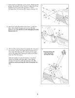
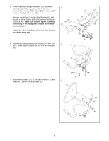
8. Push down the seat lever (not shown) on the right side of the Seat Carriage Assembly (10), slide the Seat Carriage Assembly into the Seat Rail (78), and then pull the seat lever back up. Attach a Bumper (51) to the Seat Rail (78) with an M4 x 20mm Screw (56). Next, press the Frame Rail Endcap (50) into the end of the Frame Rail (52). 8 56 51 78 52 Seat Lever 9. The Console (4) requires four 1.5V "D" batteries (not 9 included); alkaline batteries are recommended. Remove the two battery covers from the Console. Next, insert four batteries into the battery compart- ments. Make sure that the batteries are oriented as shown by the diagrams inside of the battery com- partments. Then, reattach the battery covers to the Console. Attach the Book Holder (23) to the Console (4) with two M4 x 12mm Screws (41) as shown. 10 50 Battery Covers 23 41 Batteries 4 10. While another person holds the Console (4) in the position shown, connect the wire harness on the 10 4 Console to the Upper Wire Harness (42). Insert the excess wire harness down into the Upright (2). 57 80 Attach the Console (4) to the Upright (2) with four M4 x 16mm Screws (57) and two Console Brackets (80). Be careful to avoid pinching the wire harnesses. 57 42 Wire Harness 2 7
-
 1
1 -
 2
2 -
 3
3 -
 4
4 -
 5
5 -
 6
6 -
 7
7 -
 8
8 -
 9
9 -
 10
10 -
 11
11 -
 12
12 -
13
-
14
-
15
-
16
-
17
-
18
-
19
-
20
-
21
-
22
-
23
-
24
 |
 |
