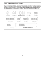
ProForm Xp440 R Bike English Manual - Page 9
Attach the Adjustment Lever to the Brake Axle
 |
View all ProForm Xp440 R Bike manuals
Add to My Manuals
Save this manual to your list of manuals |
Page 9 highlights
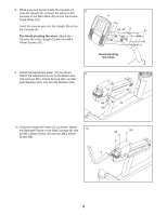
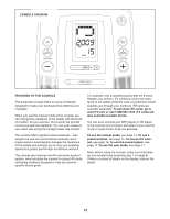
8. While a second person holds the Console (4) 8 near the Upright (2), connect the wires on the Console to the Main Wire (53) and to the Frame Pulse Wires (42). Insert the excess wire into the Upright (2) or into the Console (4). Tip: Avoid pinching the wires. Attach the Console (4) to the Upright (2) with four M4 x 16mm Screws (61). 4 53 42 2 61 61 Avoid pinching the wires 9. Orient the Adjustment Lever (15) as shown. 9 Attach the Adjustment Lever to the Brake Axle (16) with two M6 x 16mm Screws (60), two M6 Split Washers (63), and two M6 Washers (64). 16 63 64 15 60 10. Orient the Backrest Frame (5) as shown. Attach the Backrest Frame to the Seat Carriage (3) with 10 an M8 x 20mm Screw (55) and an M8 x 30mm Screw (56). 55 56 3 5 9
-
 1
1 -
2
-
3
-
 4
4 -
 5
5 -
 6
6 -
 7
7 -
 8
8 -
 9
9 -
 10
10 -
 11
11 -
 12
12 -
 13
13 -
 14
14 -
15
-
16
-
17
-
18
-
19
-
20
-
21
-
22
-
23
-
24
 |
 |
9
53
4
2
61
61
42
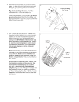
8.
While a second person holds the Console (4)
near the Upright (2), connect the wires on the
Console to the Main Wire (53) and to the Frame
Pulse Wires (42).
Insert the excess wire into the Upright (2) or into
the Console (4).
Tip: Avoid pinching the wires.
Attach the
Console (4) to the Upright (2) with four M4 x
16mm Screws (61).
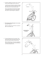
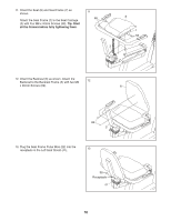
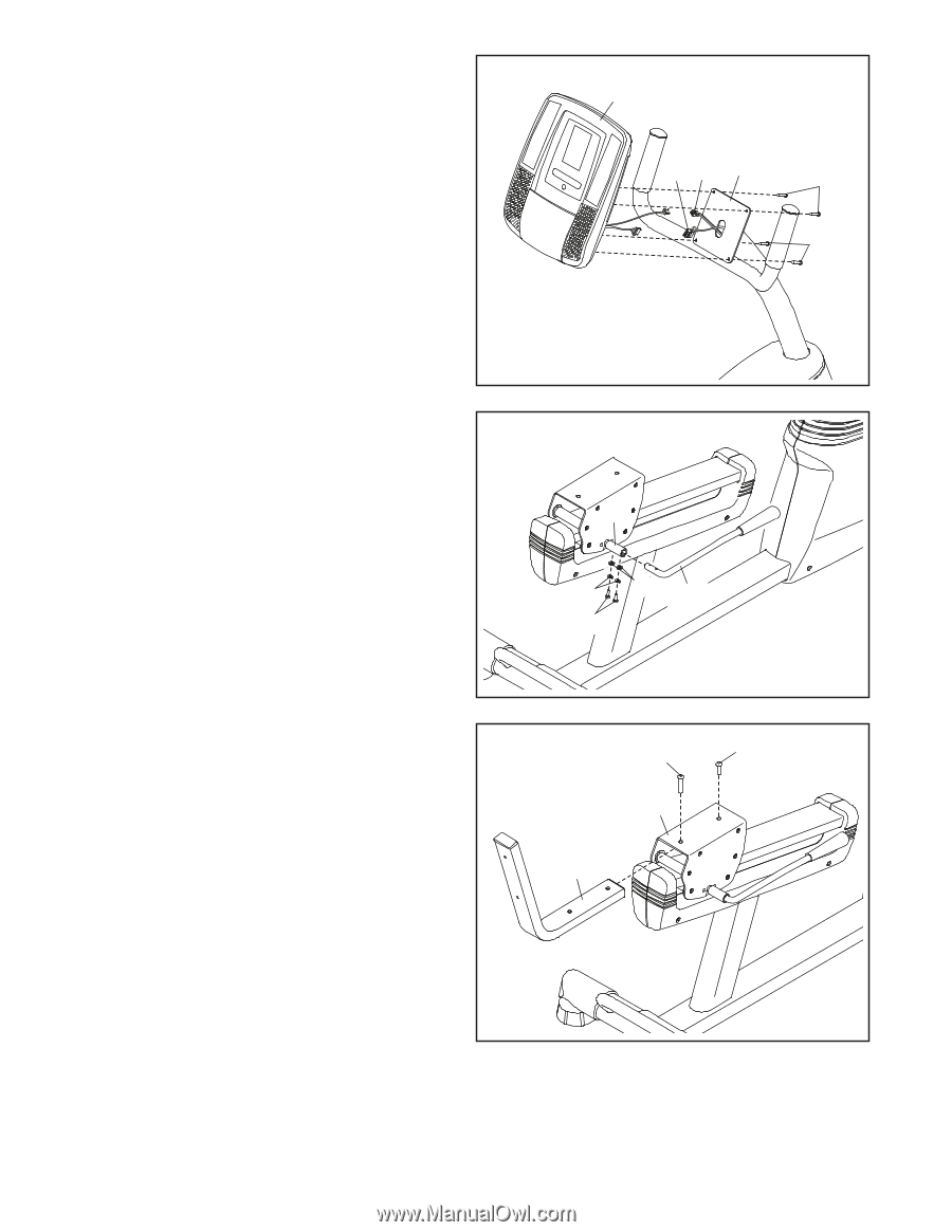
10. Orient the Backrest Frame (5) as shown. Attach
the Backrest Frame to the Seat Carriage (3) with
an M8 x 20mm Screw (55) and an M8 x 30mm
Screw (56).
Avoid pinching
the wires
10
56
5
3
55
16
15
63
64
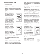
9.
Orient the Adjustment Lever (15) as shown.
Attach the Adjustment Lever to the Brake Axle
(16) with two M6 x 16mm Screws (60), two M6
Split Washers (63), and two M6 Washers (64).
60
8
9