RCA VH126N Owner/User Manual - Page 1
RCA VH126N Manual
 |
UPC - 044476060786
View all RCA VH126N manuals
Add to My Manuals
Save this manual to your list of manuals |
Page 1 highlights
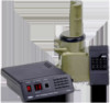
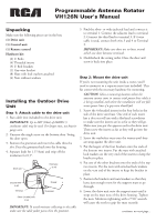
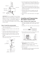
Programmable Antenna Rotator VH126N User's Manual Unpacking Make sure the following pieces are in the box: (1) Drive unit (1) Control unit (1) Remote control Hardware kit: (2) U Bolts (4) Threaded inserts (3) U Bolt brackets (1) Guy wire bracket (8) Nuts with lock washers attached (4) Nuts without washers Installing the Outdoor Drive Unit Step 1: Attach cable to the drive unit 1. Run cable (not included) to the drive unit. IMPORTANT: Up to 280' (84m) of 20AWG 3 conductor cable may be used. For longer runs, use heavier gauge wire. 2. Unscrew the single screw on the bottom door. Swing the door open. 3. Remove the grommet and insert the cable thru the slot. Press the grommet back into the housing. 4. Separate leads for 1.5"(4cm) and strip off the insulation for 0.5". Drive unit Third wire to #3 3 2 Second wire 1 to #2 Terminal Silver (or wide) wire to #1 Cover Grommet IMPORTANT: To avoid moisture collecting in the cable make sure the cable jacket passes thru the grommet. 5. Find the silver- or wide-jacketed lead and connect it to terminal 1. Connect the adjacent lead to terminal 2. Connect the third lead to terminal 3. If 4 wire cable is used, connect both wire 3 and 4 to Terminal 3. IMPORTANT: Make sure there are no loose strands which can short between terminals. 6. Doublecheck the wiring order. Close the door and screw it back into place. Step 2: Mount the drive unit If you're not mounting the unit inside a tower, you'll need to mount it to a separate mast (not included). This kit comes with the necessary hardware for mounting. CAUTION: Select a mounting location where the antenna cannot come in contact with power lines while it is being installed, and where the installation will not fall across power lines if a guy wire should fail. 1. Screw the 4 threaded inserts in the four holes in the side of the drive unit base. One end of each insert has a slot you will use with a flat-head screwdriver to make sure the inserts are in as far as they will go. Make sure you put the opposite end in the drive unit. Then screw the inserts as far as they will go into the drive unit. 2. Screw the washerless nuts onto the inserts until they are snug against the drive unit. 3. Put the largest of the four brackets onto the ends of the bottom two inserts. Put the nuts with attached lock washers on the very end of the inserts to keep the bracket in place. 4. Put one of the other brackets onto the ends of the top two inserts. Put the nuts with attached lock washers on the very end of the inserts to keep the bracket in place. 5. Position the brackets and nuts/washers so that they leave just enough room for the support mast to go through. 6. Lower the drive unit onto the support mast until it stops on the mast nose of the drive housing. Tighten the nuts. Moderate tightening with a 7/16" wrench will cause the teeth to grip the mast securely. continues on next page...
-
 1
1 -
 2
2 -
 3
3 -
 4
4 -
 5
5
 |
 |