Reebok Cyc12 English Manual - Page 5
Wire Harness 16 to the Lower Wire Harness 77.
 |
View all Reebok Cyc12 manuals
Add to My Manuals
Save this manual to your list of manuals |
Page 5 highlights
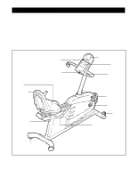
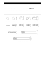
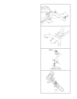
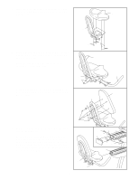
1. Identify the Front Stabilizer (2), which has Wheels 1 (75) near its ends. Attach the Front Stabilizer to the front of the Frame (1) with two M10 x 75mm Carriage Bolts (72) and two M10 Nylon Locknuts (45). Make sure that the Front Stabilizer is turned so the Wheels are not touching the floor. 2. Attach the Rear Stabilizer (3) to the rear of the 2 Frame (1) with two M10 x 82mm Carriage Bolts (63) and two M10 Nylon Locknuts (45). 75 2 1 45 1 3 45 72 75 45 3. While a second person holds the Handlebar Post (6) 3 near the Frame (1) as shown, connect the Upper Wire Harness (16) to the Lower Wire Harness (77). Carefully slide the Handlebar Post (6) onto the Frame (1); be careful to avoid pinching the Wire Harnesses (16, 77). Attach the Handlebar Post to the Frame with four M8 x 25mm Button Screws (27) and four M8 Split Washers (70). 4. Connect the two Pulse Wires (86) to the two wires 4 extending from the Console (9). Next, connect the Upper Wire Harness (16) to the back of the Console. Insert all wires into the Handlebar Post (6). Attach the Console (9) to the Handlebar Post (6) with four M4 x 16mm Screws (90). Be careful to avoid pinching the wires. 5 63 6 70 27 70 16 27 77 1 9 Console Wires 86 16 6 90
-
 1
1 -
 2
2 -
 3
3 -
 4
4 -
 5
5 -
 6
6 -
 7
7 -
 8
8 -
 9
9 -
 10
10 -
 11
11 -
12
-
13
-
14
-
15
-
16
 |
 |
