Reebok Cyc31 Uk Manual - Page 6
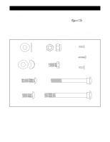
two M8 x 70mm Carriage Bolts 47, two M8 Curved
 |
View all Reebok Cyc31 manuals
Add to My Manuals
Save this manual to your list of manuals |
Page 6 highlights
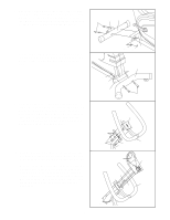
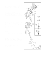
1. Attach the Front Stabiliser (2) to the Frame (1) with two M8 x 70mm Carriage Bolts (47), two M8 Curved Washers (28), and two M8 Black Nylon Locknuts (56). Make sure that the Front Stabiliser is turned so the Roller (50) is not touching the floor. 1 47 50 2 2. Attach the Rear Stabiliser (3) to the Frame (1) with 2 two M8 x 80mm Carriage Bolts (63), two M8 Curved Washers (28), and two M8 Black Nylon Locknuts (56). 28 56 1 3 3. Hold the Handlebar (7) near the Handlebar Post (6). 3 Insert the Extension Wire (22) through the hole in the Handlebar. Attach the Handlebar to the Handlebar Post with three M8 x 20mm Button Screws (19) and three M8 Flat Washers (18). Make sure that the Extension Wire (22) is not pinched between the Handlebar and the Handlebar Post. 56 28 1 63 Hole 22 18 4. Hold the Console Plate (8) near the Handlebar (7). 4 Insert the Resistance Cable (16) down into the hole in the Handlebar and through the Handlebar Post (6). Next, thread the Extension Wire (22) up through the indicated hole in the Console Plate (8). Attach the Console Plate to the Handlebar (7) with four M4 x 10mm Screws (21). Make sure that the Extension Wire (22) and the Resistance Cable (16) are not pinched between the Console Plate and the Handlebar. 19 6 18 8 22 Hole 16 7 Hole 7 6 21 6
-
 1
1 -
 2
2 -
 3
3 -
 4
4 -
 5
5 -
 6
6 -
 7
7 -
 8
8 -
 9
9 -
 10
10 -
 11
11 -
 12
12 -
13
-
14
-
15
-
16
 |
 |
