Reebok Rst 250 English Manual - Page 7
Tighten the M10 Nylon Locknuts 35 used
 |
View all Reebok Rst 250 manuals
Add to My Manuals
Save this manual to your list of manuals |
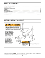
Page 7 highlights
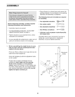
2. Attach the Frame (1) to the Crossbar (3) with two M10 x 95mm Bolts (34) and two M10 Nylon Locknuts (35). Do not tighten the Nylon Locknuts yet. Press two 8mm Bushings (32) into the indicated locations on the Frame (1). Press a 75mm x 50mm Inner Cap (20) into the Frame (1). 2 34 20 32 1 32 35 3 3. Press two 50mm Square Inner Caps (22) into the Front Stabilizer (2). 3 Attach the Front Stabilizer (2) to the Frame (1) with two M10 x 65mm Bolts (36), two M10 Washers (27), and two M10 Nylon Locknuts (35). 1 35 2 Tighten the M10 Nylon Locknuts (35) used in steps 1-3. 22 36 27 22 4. Press four 20mm x 40mm Inner Caps (43) into the Backrest Frames (10). Orient the Backrest 4 Frames as shown. Note: The indents in the 8 Backrest Frames must be on top. Attach the Backrest Bracket (9) to the Backrest Frames (10) with four M8 x 55mm Carriage Bolts (40) and four M8 Nylon Locknuts (42). Do not tighten the Nylon Locknuts yet. Attach the Backrest (8) to the Backrest Frames (10) with four M6 x 50mm Bolts (39) and four M6 Washers (19). Do not tighten the Bolts yet. The Backrest must be oriented as shown. 5. Screw the Backrest Adjustment Knob (30) into the Frame (1). Pull the Knob out as far as it will go 5 and lower the Backrest Bracket (9) between the two tubes on the Bench Frame. Snap the Knob into an adjustment hole in the Backrest Bracket. Indent 10 43 19 39 9 8 Lubricate an M10 x 140mm Bolt (37). Attach the indicated holes in the Backrest Frames (10) and the two Plastic Plates (26) to the Bench Frame (1) with the Bolt, two M10 Washers (27), and an M10 Nylon Locknut (35). Note: The warning decals on the Plastic Plates must face away from the bench. Do not overtighten the M10 Nylon Locknut; the Backrest (8) must be able to pivot easily. 7 10 Hole 9 Adjustment Hole 40 43 19 39 42 42 30 35 27 26 27 1 Decal 26 37 Lubricate
-
 1
1 -
 2
2 -
 3
3 -
 4
4 -
 5
5 -
 6
6 -
 7
7 -
 8
8 -
 9
9 -
 10
10 -
 11
11 -
 12
12 -
13
-
14
-
15
-
16
 |
 |
