Rheem RARL-JEC Installation Instructions - Page 17
Comfort Control, System™
 |
View all Rheem RARL-JEC manuals
Add to My Manuals
Save this manual to your list of manuals |
Page 17 highlights
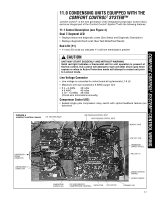
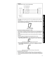
COMFORT CONTROL2 SYSTEM™ CONTROL WIRING 11.0 CONDENSING UNITS EQUIPPED WITH THE 11.0 COMFORT CONTROL2 SYSTEM™ Comfort Control2 is the next generation of the Integrated Compressor Control (ICC) and is an integral part of the Comfort Control2 System™ with the following features: 11.1 Control Description (see Figure 4) Dual 7-Segment LED • Displays status and diagnostic codes (See Status and Diagnostic Description) • Displays diagnostic/fault recall (See Test Mode/Fault Recall) Red LED (Y1) • Y1 red LED (solid on) indicates Y1 call from thermostat is present ! CAUTION UNIT MAY START SUDDENLY AND WITHOUT WARNING Solid red light indicates a thermostat call for unit operation is present at the ICC control. ICC control will attempt to start unit after short cycle timer expires or when in Active Protection mode will attempt to restart unit prior to Lockout mode. Line Voltage Connector • Line voltage is connected to control board at lug terminals L1 & L2 • Maximum wire size accepted is 6 AWG copper wire • # 4 - 6 AWG 45 in/lbs # 8 AWG 40 in/lbs # 10 - 14 AWG 35 in/lbs (Check wire terminations annually) Compressor Control (K2) • Sealed single pole compressor relay switch with optical feedback feature (arc detection) FIGURE 4 COMFORT CONTROL2 BOARD O.D. FAN (OFM) RELAY LOW PRESSURE CONTROL INPUT HIGH PRESSURE CONTROL INPUT MEMORY CARD COMPRESSOR WIRING { CONNECTOR LINE VOLTAGE CONNECTION LOW VOLT FUSE THERMOSTAT CONNECTION (E2) RED LED (Y1) COMPRESSOR CONTROL (K2) ICC (INTEGRATED COMPRESSOR CONTROL) SW2 BUTTON TEST BUTTON AMBIENT DEFROST CONTROL DEFROST SENSOR 7-SEGMENT LED 17
-
 1
1 -
2
-
3
-
4
-
5
-
6
-
7
-
8
-
9
-
10
-
11
-
 12
12 -
 13
13 -
 14
14 -
 15
15 -
 16
16 -
 17
17 -
 18
18 -
 19
19 -
 20
20 -
 21
21 -
 22
22 -
23
-
24
-
25
-
26
-
27
-
28
-
29
-
30
-
31
-
32
-
33
-
34
-
35
-
36
-
37
-
38
-
39
-
40
-
41
-
42
-
43
-
44
-
45
-
46
-
47
-
48
 |
 |
