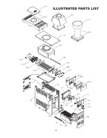
Rheem Versa Heaters Operating Instructions - Page 30
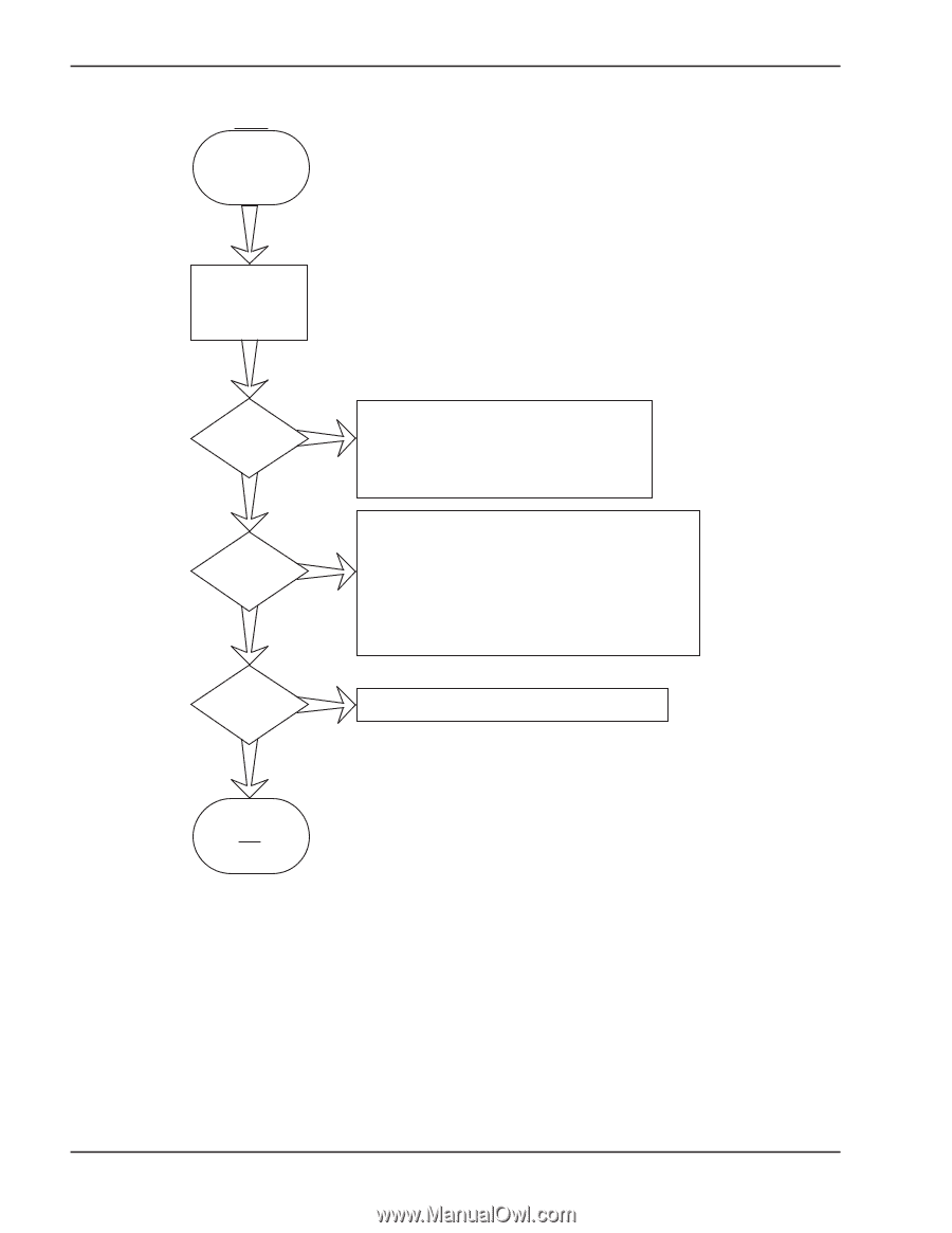
Electronic Control Logic Flowchart, General-Heater Will Not Fire
 |
View all Rheem Versa Heaters manuals
Add to My Manuals
Save this manual to your list of manuals |
Page 30 highlights
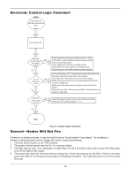
Electronic Control Logic Flowchart START Turn knob to a desired temperature zone. Turn switch ON. After (6) seconds, does No the igniter spark? Yes Does the No burner tray light? Yes •Check water flow. Pressure switch is set for 1.75 PSI. •Turn knob counterclockwise (setpoint may be lower than actual temperature) •Check High Limit. Both are normally closed. •Check Roll-Out switch. Must be normally closed. •Check wiring in control box against wiring diagram. Ensure the heater is OFF. Attempt each step individually and manually restart the heater after each attempt. •Check gas line. There may be some air in the system. •Make sure high tension wire is not grounding out to metal or other voltage wire. •Make sure high tension wire is properly connected to the igniter. •Check the gas valve. There must be 24VAC while the ignition module is sparking. Does the burner tray stay lit? No •Check the igniter. Igniter may not be sensing correctly. Check that the spark plug gap is ~.18". Yes END Fig. 37: Control Logic Flowchart General-Heater Will Not Fire If there is no electrical power, it may be that the home "circuit breaker" has tripped. Try re-setting it. If there is electrical power but the heater will not fire check the following: 1. The time clock must be in the "ON" position. 2. The pump strainer basket may be full. If so remove debris. 3. The filter may be dirty. If so, backwash or clean filter. (To tell if the filter is dirty, look to see if the filter pres- sure will be higher than usual). 4. The pump may have lost its prime and be running dry. Check the pressure on the filter. If there is no pres- sure; then there is not enough moving water (or the gauge is broken). Try to get the pump to run at its normal flow rate. 30
-
 1
1 -
2
-
3
-
4
-
5
-
6
-
7
-
8
-
9
-
10
-
11
-
12
-
13
-
14
-
15
-
16
-
17
-
18
-
19
-
20
-
21
-
22
-
23
-
24
-
 25
25 -
 26
26 -
 27
27 -
 28
28 -
 29
29 -
 30
30 -
 31
31 -
 32
32 -
 33
33 -
 34
34 -
 35
35 -
36
 |
 |