Ryobi ACTIL04 Operation Manual
Ryobi ACTIL04 Manual
 |
View all Ryobi ACTIL04 manuals
Add to My Manuals
Save this manual to your list of manuals |
Ryobi ACTIL04 manual content summary:
- Ryobi ACTIL04 | Operation Manual - Page 1
manual for their cultivator before using this accessory. Save these instructions. Refer to them frequently and use them to instruct you are not comfortable performing any of the functions described in these instructions, take your unit to a qualified service center. Fig. 1 C A C B F C C D - Ryobi ACTIL04 | Operation Manual - Page 2
accompagné de ces instructions. ADVERTENCIA: Para reducir el riesgo de lesiones, el usuario debe leer y comprender el manual del operador de les présentes directives, veuillez apporter votre unité à un centre de service qualifié. AVERTISSEMENT : Protégez toujours vos mains en portant des gants é
-
 1
1 -
 2
2
 |
 |
WARNING:
To reduce the risk of injury, user must read and under-
stand the operator’s manual for their cultivator before
using this accessory. Save these instructions. Refer to
them frequently and use them to instruct other users. If
you loan someone this product, loan them these instruc-
tions also.
WARNING:
Ensure compatibility and fit before using this accessory.
Do not use this accessory if a part is damaged or missing.
If you are not comfortable performing any of the func-
tions described in these instructions, take your unit to a
qualified service center.
WARNING:
Always protect hands by wearing heavy gloves and/or
wrapping the cutting edges of the tines with rags and
other material when installing or removing tines. Contact
with the tines could result in serious personal injury.
REMOVING AND REPLACING THE TINES
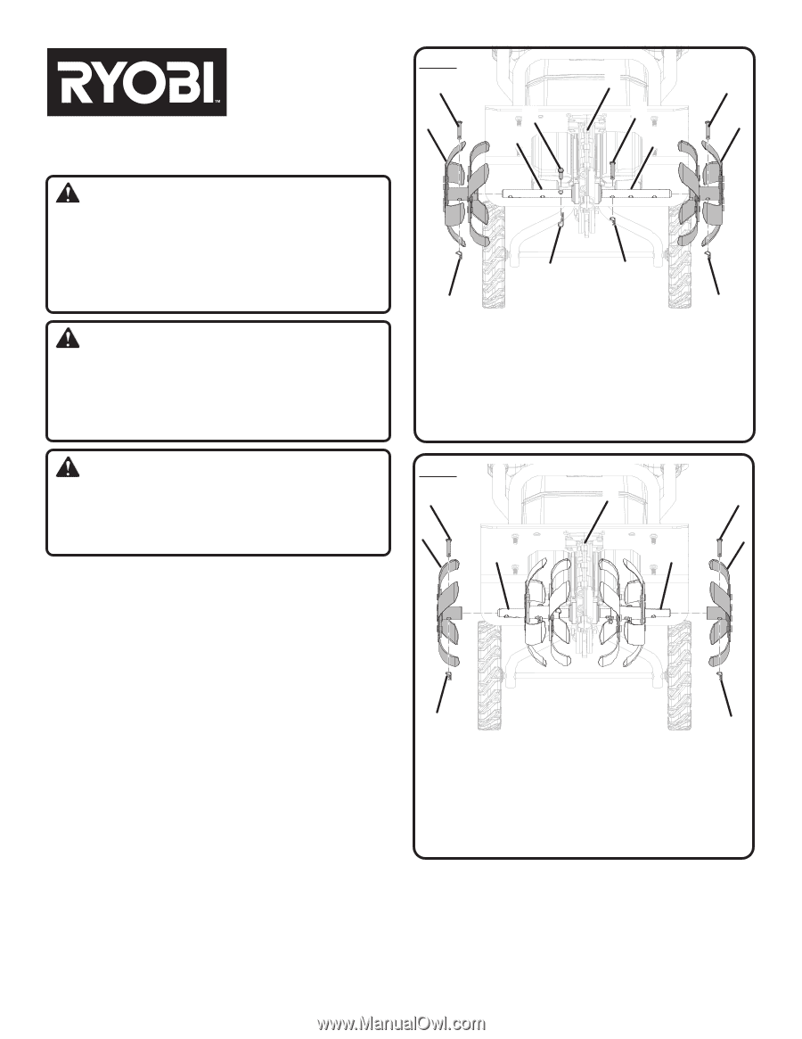
See Figures 1 - 2.
With user facing the front of the tiller, the left outer tine
assembly is marked “A”. The left inner tine assembly is
marked “B”. The right inner tine is marked “C” and the right
outer tine is marked “D”. For correct operation of the unit,
the tines must be installed in the correct position.
Remove the protective caps from tines.
Insert shear pins through the holes in the tine shaft closest
to the gear box. Secure with cotter pins.
Place the inner tine assemblies marked “B” and “C” on
the tine shaft as shown.
Align the notches of the inner tine assemblies with the
heads of the shear pins.
NOTE:
You may have to rotate the tine assemblies until
the holes in the assemblies are aligned with the holes in
the tine shaft. If the holes do not align, the tine assemblies
may be installed on the wrong sides. Reverse the position
of the tine assemblies and check for hole alignment. When
installed correctly, the “C” on the right inner tine assembly
should be closer to the gear box than the “B” on the left
inner tine assembly.
Insert shear pins through the holes in the inner tine
assemblies and the shaft. Secure with cotter pins.
FOR USE WITH RY40703 RYOBI 40 VOLT
FRONT TINE TILLER
ACTIL04
REPLACEMENT
TINES
Fig. 1
Fig. 2
E
E
E
E
E
E
C
C
C
C
A
A
D
D
A - Left outer tine assembly (assemblage de dent extérieure gauche «
A », conjunto de púas exterior izquierda “A”)
B - Tine shaft (arbre de dents, eje de las púas)
C - Shear pin (goupille de sécurité, pasadore de seguridad)
D - Right outer tine assembly (assemblage de dent extérieure droite,
conjunto de púas exterior derecho)
E - Cotter pin (goupille fendue, clavija)
F - Gear box (boîte de transmission, caja de engranajes)
A - Left outer tine assembly (assemblage de dent extérieure gauche,
conjunto de púas exterior izquierdo)
B - Tine shaft (arbre de dents, eje de las púas)
C - Shear pin (goupille de sécurité, pasadore de seguridad)
D - Right outer tine assembly (right assemblage de dent extérieure
droite « D », conjunto de púas exterior derecho “D”)
E - Cotter pin (goupille fendue, clavija)
F - Gear box (boîte de transmission, caja de engranajes)
B
C
B
B
B
F
C
F
Place the outer tine marked “D” on the right side of the
tine shaft and the outer tine marked “A” on the left side
of the shaft.
Rotate the outer tines until the holes in the tines are
aligned with the holes in the tine shaft.
Insert shear pins through the holes in the outer tine
assemblies and the shaft. Secure with cotter pins.