Ryobi AG452K English Manual - Page 15
Guard Replacement
 |
View all Ryobi AG452K manuals
Add to My Manuals
Save this manual to your list of manuals |
Page 15 highlights
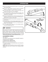
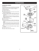
MAINTENANCE GUARD REPLACEMENT See Figure 13. After extended use, the guard may become worn and need adjustment or replacing. Or, if you drop the angle grinder and damage the guard, it may be necessary to replace it. To replace the guard: Unplug the angle grinder. Depress spindle lock button and rotate nut with provided wrench until spindle locks. Using the wrench provided, loosen and remove nut, grinding or accessory wheel, and disc flange from spindle if necessary. NOTE: To prevent damage to the spindle or spindle lock, always allow motor to come to a complete stop before engaging spindle lock. Unlock the guard clamp lever. Remove the guard. Place the new guard on the shoulder of the bearing cap, aligning the arrow with the slot on the bottom of the angle grinder. NOTE: If the new guard will not fit, loosen the clamp screw until it will slide over the bearing cap. Be sure the tabs on the guard are seated in the groove in the bearing cap. Rotate guard to the correct position as shown in figures 9 and 10. Lock the guard clamp lever. Tighten clamp screw securely if needed. to tighten to loosen Disc Flange Wrench FLANGE Nut Grinding Wheel GUARD CLAMP LEVER arrow BEARING CAP Guard Clamp Screw Spindle Spindle Lock Button Fig. 13 15
-
 1
1 -
2
-
3
-
4
-
5
-
6
-
7
-
8
-
9
-
 10
10 -
 11
11 -
 12
12 -
 13
13 -
 14
14 -
 15
15 -
 16
16
 |
 |
