Ryobi JS451L English Manual - Page 11
Operation
 |
View all Ryobi JS451L manuals
Add to My Manuals
Save this manual to your list of manuals |
Page 11 highlights
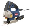
OPERATION LOCK-ON BUTTON See Figure 4. The saw is equipped with a lock-on feature which is convenient when continuous cutting for extended periods of time is required. To lock-on: Depress the switch trigger. Push in and hold the lock-on button located on the side of the handle. Release switch trigger. Release lock-on button. To release: Depress the switch trigger to release. If you have the lock-on feature engaged during use and the saw becomes disconnected from power supply, disengage the lock-on feature immediately. LOCK-ON BUTTON switch trigger Fig. 4 WARNING: Before connecting the saw to power supply source, always check to be sure it is not in lock-on position (depress and release switch trigger). Failure to do so could result in accidental starting of the saw resulting in possible serious injury. Also, do not lock the trigger on jobs where the saw may need to be stopped suddenly. SPLINTER-FREE CUTTING See Figure 5. The anti-splintering insert is especially useful when cutting plywood. It should only be used when making straight cuts or circle cuts. It is not for bevel cutting or plunge cutting. NOTE: The non-orbital setting also helps reduce splintering when cutting plywood. To attach and remove the anti-splintering insert: Unplug the saw. Set the cutting angle at 0°. To attach, slide the insert back onto the tabs on the front of the base. Make sure it snaps securely into place. To remove, grasp the anti-splintering insert and pull straight out. anti-splintering insert VARIABLE SPEED CONTROL SELECTOR Variable SpEed Control selector See Figure 6. The saw has a variable speed control selector designed to allow operator control and adjustment of speed and power limits. The speed and power of the saw can be increased or decreased by rotating the variable speed control selector in the direction of the arrows shown in figure 6. NOTE: Hold the saw in normal operating position and turn the variable speed control selector to the positive ( + ) symbol to increase speed and power. Turn to the negative ( − ) symbol to decrease speed and power. 11 - English Fig. 5 Fig. 6
-
 1
1 -
2
-
3
-
4
-
5
-
 6
6 -
 7
7 -
 8
8 -
 9
9 -
 10
10 -
 11
11 -
 12
12 -
 13
13 -
 14
14 -
 15
15 -
 16
16 -
17
-
18
-
19
-
20
 |
 |
