Ryobi P212 English Manual - Page 13
Warning, Switch Trigger, Variable Speed, Direction Of Rotation Selector, Caution, Internal Spindle
 |
View all Ryobi P212 manuals
Add to My Manuals
Save this manual to your list of manuals |
Page 13 highlights
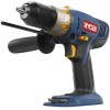
OPERATION SWITCH TRIGGER See Figure 5. To turn the drill ON, depress the switch trigger. To turn it OFF, release the switch trigger. VARIABLE SPEED The variable speed switch trigger delivers higher speed and torque with increased trigger pressure and lower speed with decreased trigger pressure. NOTE: You might hear a whistling or ringing noise from the switch during use. Do not be concerned; this is a normal part of the switch function. DIRECTION OF ROTATION SELECTOR (FORWARD/REVERSE/CENTER LOCK) See Figure 5. The direction of bit rotation is reversible and is controlled by a selector located above the switch trigger. With the drill held in normal operating position, the direction of rotation selector should be positioned to the left of the switch trigger for drilling. The drilling direction is reversed when the selector is to the right of the switch trigger. Setting the switch trigger in the OFF (center lock) position helps reduce the possibility of accidental starting when not in use. CAUTION: To prevent gear damage always allow the chuck to come to a complete stop before changing the direction of rotation. To stop the drill, release the switch trigger and allow the chuck to come to a complete stop. NOTE: The drill will not run unless the direction of rotation selector is pushed fully to the left or right. Avoid running the drill at low speeds for extended periods of time. Running at low speeds under constant usage may cause the drill to become overheated. If this occurs, cool the drill by running it without a load and at full speed. INTERNAL SPINDLE LOCK The internal spindle lock allows the user single-handed control of chuck adjustments and bit changes. Squeezing the chuck body stops the chuck jaws from turning. For bit changes and chuck adjustments, squeeze the chuck body and turn. KEYLESS CHUCK See Figure 6. The drill has a keyless chuck to tighten or release drill bits in the chuck jaws. The arrows on the chuck indicate which direction to rotate the chuck body in order to LOCK (tighten) or UNLOCK (release) the drill bit. DIRECTION OF ROTATION SELECTOR (FORWARD/REVERSE/CENTER LOCK) REVERSE UNLOCK (RELEASE) FORWARD SWITCH TRIGGER Fig. 5 KEYLESS CHUCK LOCK (TIGHTEN) Fig. 6 WARNING: Do not hold chuck body with one hand and use power of the drill to tighten the chuck jaws on the drill bit. The chuck body could slip in your hand, or your hand could slip and come in contact with the rotating drill bit. This could cause an accident resulting in serious personal injury. 13
-
 1
1 -
2
-
3
-
4
-
5
-
6
-
7
-
 8
8 -
 9
9 -
 10
10 -
 11
11 -
 12
12 -
 13
13 -
 14
14 -
 15
15 -
 16
16 -
 17
17 -
 18
18 -
19
-
20
-
21
-
22
 |
 |
