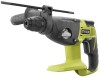
Ryobi P221 Operation Manual - Page 9
Removing The Bit From The Sds Plus - one sds hammer drill
 |
View all Ryobi P221 manuals
Add to My Manuals
Save this manual to your list of manuals |
Page 9 highlights
OPERATION CAUTION: To prevent gear damage, always allow the chuck to come to a complete stop before changing the direction of rotation. To stop the drill, release the switch trigger and allow the chuck to come to a complete stop. NOTE: The drill will not run unless the direction of rotation selector is pushed fully to the left or right. Avoid running the drill at low speeds for extended periods of time. Running at low speeds under constant usage may cause the drill to become overheated. If this occurs, cool the drill by running it without a load and at full speed. USING THE AUXILIARY HANDLE ASSEMBLY See Figures 5 - 6, page 13. An auxiliary handle is packed with the drill for ease of operation and to help prevent loss of control. The handle can be mounted on the opposite side for left or right hand use. ADJUSTING THE AUXILIARY HANDLE ASSEMBLY See Figure 5, page 13. Loosen the auxiliary handle by turning the auxiliary handle counterclockwise. Insert the auxiliary handle assembly in the desired operating position. Securely tighten by turning the auxiliary handle clockwise. NOTE: Be sure the auxiliary handle is securely tightened against the depth stop rod clamp. This secures the depth stop rod at the desired depth of cut. It also secures the auxiliary handle. ADJUSTING THE DEPTH STOP ROD See Figures 4 - 5, pages 12 - 13. The depth stop rod helps control the depth of drilled holes. For convenience and ease of starting threads, the hex nut has been trapped inside the molded slot in the auxiliary handle. To adjust the depth stop rod: Lock the switch trigger by placing the direction of rotation selector in the center position. Loosen the auxiliary handle assembly by turning the auxiliary handle counterclockwise. Adjust the depth stop rod so that the drill bit extends beyond the end of the rod to the required drilling depth. Tighten the auxiliary handle assembly by turning the auxiliary handle clockwise. NOTE: When properly installed, the teeth on the depth stop rod should be aligned with the teeth indicator on the depth stop rod clamp. FITTING AND CHANGING SDS BIT See Figure 6, page 13. This tool is equipped with an SDS Plus connection system. Clean the bit and grease it with machine grease before inserting it into the chuck. Pull back the clamp collar and hold it. Push and rotate the dust-free tool into the bit holder as far as it will go. Release the clamp collar to lock the bit. Check that bit has locked by pulling on it. REMOVING THE BIT FROM THE SDS PLUS SYSTEM See Figure 6, page 13. Pull back the clamp collar and remove the bit. CHUCK ADAPTOR (NOT INCLUDED) See Figure 7, page 13. For drilling in metal, wood, and plastic with drill bits that have non-SDS Plus shaft, a chuck adaptor is available. SLIP CLUTCH If the tool becomes jammed or gets caught, the slip clutch releases. Remove the load from the machine immediately by pulling back the drill. MODE SELECTOR See Figure 8, page 13. The mode selector allows you to quickly switch from rotary mode to hammer mode. In general, rotary mode should be used for drilling and other heavy duty applications. Hammer mode should be used for hammer drilling. For drilling, place the selector in the ( ) position. For hammer drilling, set mode selector to ( ). Switch between modes when tool is at a standstill. NOTE: Hammer drilling mode will damage the tool's mechanism when used for fastening or drilling by non-SDS Plus bits. Select the rotary mode only on such purpose. When hammer drilling, use only bits with hard metal and SDS Plus shaft only. The use of commercially available masonry bits with cylindrical shaft by means of the drill adaptor is impossible. CAUTION: When hammer drilling, do not apply too much pressure. Too much pressure will place unnecessary load on the motor. 9 - English
-
 1
1 -
2
-
3
-
 4
4 -
 5
5 -
 6
6 -
 7
7 -
 8
8 -
 9
9 -
 10
10 -
 11
11 -
 12
12 -
 13
13 -
 14
14 -
15
-
16
-
17
-
18
-
19
-
20
-
21
-
22
-
23
-
24
-
25
-
26
-
27
-
28
-
29
-
30
-
31
-
32
-
33
-
34
-
35
-
36
 |
 |
