Ryobi P818 User Manual - Page 10

Assembly

Page 10 highlights

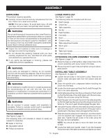
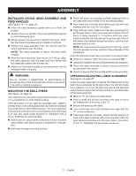
ASSEMBLY UNPACKING This product requires assembly.  Carefully remove the tool and any accessories from the box. Place it on a level work surface. NOTE: This tool is heavy. To avoid back injury, lift with your legs, not your back, and get help when needed. WARNING: Do not use this product if any parts on the Loose Parts List are already assembled to your product when you unpack it. Parts on this list are not assembled to the product by the manufacturer and require customer installation. Use of a product that may have been improperly assembled could result in serious personal injury.  Inspect the tool carefully to make sure no breakage or damage occurred during shipping.  Do not discard the packing material until you have carefully inspected the tool, identified all loose parts, and satisfactorily operated the tool.  If any parts are damaged or missing, please call 1-800-525-2579 for assistance. WARNING: If any parts are damaged or missing, do not operate this tool until the parts are replaced. Use of this product with damaged or missing parts could result in serious personal injury. WARNING: Do not attempt to modify this tool or create accessories not recommended for use with this tool. Any such alteration or modification is misuse and could result in a hazardous condition leading to possible serious personal injury. WARNING: Do not connect to power supply until assembly is complete. Failure to comply could result in accidental starting and possible serious personal injury. TOOLS NEEDED See Figure 3, page 17. The following tools (not included or drawn to scale) are needed for assembly:  Mallet or hammer  Adjustable wrench  Phillips screwdriver LOOSE PARTS LIST See Figure 4, page 18. The following items are included with the tool:  Depth gauge 1  Chuck key 1  Table assembly 1  Hex key 1  Feed handles 3  Hex bolts 3  Base 1  Column collar 1  Table adjustment handle 1  Worm gear 1  Chuck 1  Table lock handle 1  Head assembly 1 ATTACHING COLUMN ASSEMBLY TO BASE See Figure 5, page 19.  Place the base on a flat surface. Align screw holes in the column assembly with screw holes in the base.  Place a hex bolt in each hole and tighten using an adjust- able wrench. INSTALLING TABLE ASSEMBLY See Figures 6 - 9, page 19. ■ Loosen the set screw in the column collar. Remove the column collar and gear rack from the column and set aside.  Clean the spindle with a degreaser before installing the chuck into the head.  Locate the worm gear and feed the D-shaft through the hole in the table assembly.  Install table adjustment handle over the end of the D-shaft so that the flat side of the shaft aligns with the set screw. Tighten the set screw using the hex key.  Feed the gear rack through the slot in the table assembly so that the teeth are facing out and the longer smooth end faces up. The worm gear should engage the gear rack.  Using both hands, slide the entire table assembly and gear rack onto the column until the bottom of the gear rack is positioned in the base collar and against the column.  Slide the column collar, bevel-side down, over the column until the beveled side engages the beveled end of the gear rack. Tighten the set screw in the collar using the hex key. Do not overtighten. NOTE: You should be able to move the table from side to side.  Locate the table lock handle. Insert it into the threaded hole at the rear of the table assembly and tighten by hand. 10 - English

  • 1
  • 2
  • 3
  • 4
  • 5
  • 6
  • 7
  • 8
  • 9
  • 10
  • 11
  • 12
  • 13
  • 14
  • 15
  • 16
  • 17
  • 18
  • 19
  • 20
  • 21
  • 22
  • 23
  • 24
  • 25
  • 26
  • 27
  • 28
  • 29
  • 30
  • 31
  • 32
  • 33
  • 34
  • 35
  • 36
  • 37
  • 38
  • 39
  • 40
  • 41
  • 42
  • 43
  • 44
  • 45
  • 46
  • 47
  • 48
  • 49
  • 50
  • 51
  • 52
  • 53
  • 54
  • 55
  • 56

10 - English
UNPACKING
This product requires assembly.
Carefully remove the tool and any accessories from the
box. Place it on a level work surface.
NOTE:
This tool is heavy. To avoid back injury, lift with
your legs, not your back, and get help when needed.
WARNING:
Do not use this product if any parts on the Loose Parts List
are already assembled to your product when you unpack
it. Parts on this list are not assembled to the product by
the manufacturer and require customer installation. Use
of a product that may have been improperly assembled
could result in serious personal injury.
Inspect the tool carefully to make sure no breakage or
damage occurred during shipping.
Do not discard the packing material until you have
carefully inspected the tool, identified all loose parts,
and satisfactorily operated the tool.
If any parts are damaged or missing, please call
1-800-525-2579 for assistance.
WARNING:
If any parts are damaged or missing, do not operate
this tool until the parts are replaced. Use of this product
with damaged or missing parts could result in serious
personal injury
.
WARNING:
Do not attempt to modify this tool or create accessories
not recommended for use with this tool. Any such
alteration or modification is misuse and could result in a
hazardous condition leading to possible serious personal
injury.
WARNING:
Do not connect to power supply until assembly is
complete. Failure to comply could result in accidental
starting and possible serious personal injury.
TOOLS NEEDED
See Figure 3, page 17.
The following tools (not included or drawn to scale) are
needed for assembly:
Mallet or hammer
Adjustable wrench
Phillips screwdriver
ASSEMBLY
LOOSE PARTS LIST
See Figure 4, page 18.
The following items are included with the tool:
Depth gauge
...............................................................
1
Chuck key
..................................................................
1
Table assembly
...........................................................
1
Hex key
........................................................................
1
Feed handles
..............................................................
3
Hex bolts
....................................................................
3
Base
...........................................................................
1
Column collar
.............................................................
1
Table adjustment handle
............................................
1
Worm gear
..................................................................
1
Chuck
.........................................................................
1
Table lock handle
.......................................................
1
Head assembly
..........................................................
1
ATTACHING COLUMN ASSEMBLY TO BASE
See Figure 5, page 19.
Place the base on a flat surface. Align screw holes in the
column assembly with screw holes in the base.
Place a hex bolt in each hole and tighten using an adjust-
able wrench.
INSTALLING TABLE ASSEMBLY
See Figures 6 - 9, page 19.
Loosen the set screw in the column collar. Remove the
column collar and gear rack from the column and set
aside.
Clean the spindle with a degreaser before installing the
chuck into the head.
Locate the worm gear and feed the D-shaft through the
hole in the table assembly.
Install table adjustment handle over the end of the D-shaft
so that the flat side of the shaft aligns with the set screw.
Tighten the set screw using the hex key.
Feed the gear rack through the slot in the table assembly
so that the teeth are facing out and the longer smooth end
faces up. The worm gear should engage the gear rack.
Using both hands, slide the entire table assembly and gear
rack onto the column until the bottom of the gear rack is
positioned in the base collar and against the column.
Slide the column collar, bevel-side down, over the column
until the beveled side engages the beveled end of the
gear rack. Tighten the set screw in the collar using the
hex key. Do not overtighten.
NOTE:
You should be able to move the table from side
to side.
Locate the table lock handle. Insert it into the threaded
hole at the rear of the table assembly and tighten by hand.