Samsung 180T User Manual (user Manual) (ver.1.0) (English) - Page 22
Pin Assignments
 |
View all Samsung 180T manuals
Add to My Manuals
Save this manual to your list of manuals |
Page 22 highlights
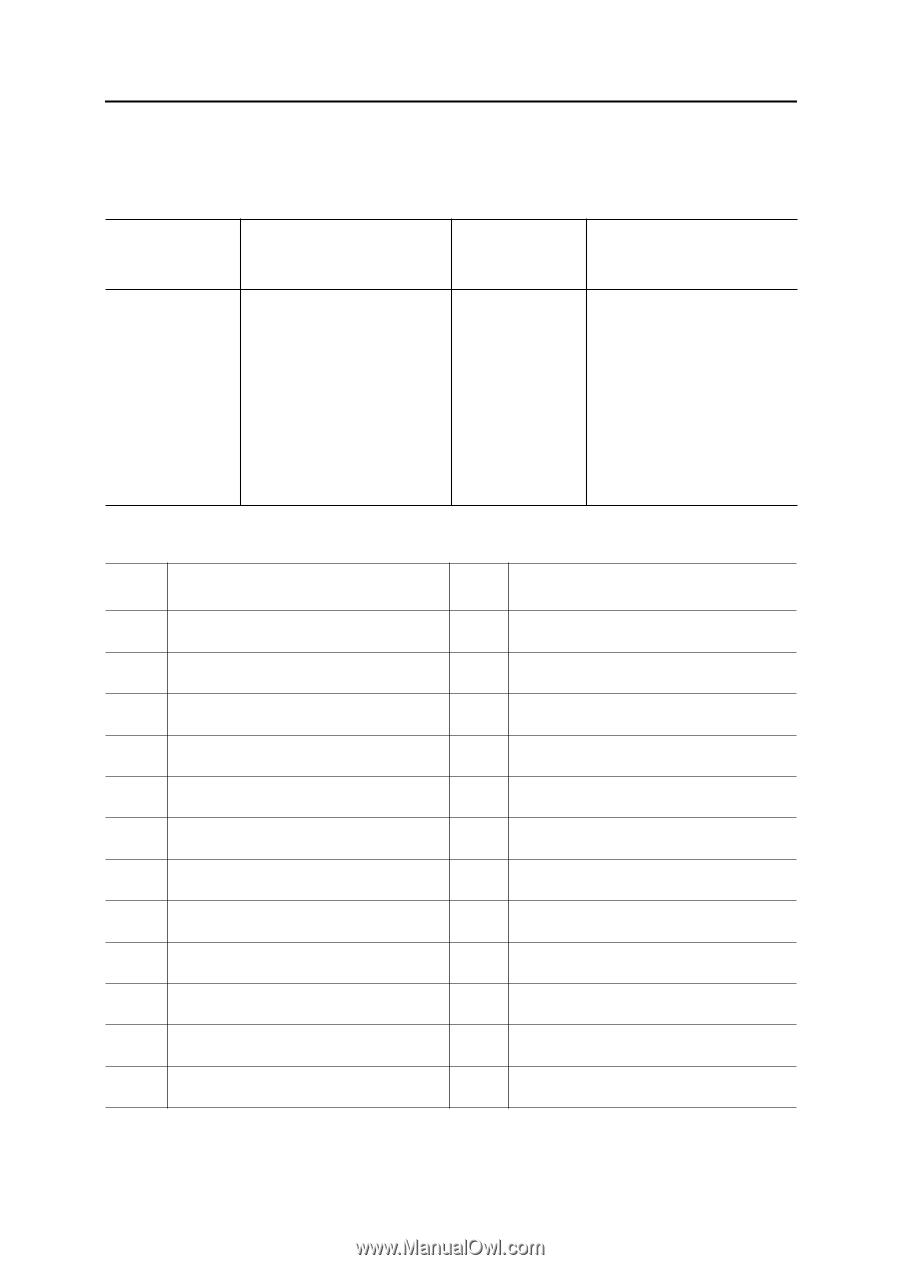
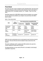
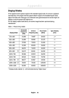
Appendix Pin Assignments Table 5. 15-Pin D-SUB connector Pin No. 1 2 3 4 5 6 7 8 15-Pin Side of the Signal Cable Red Green Blue GND GND (DDC Return) GND-R GND-G GND-B Table 6. DVI-D Connector Pin Signal Assignment 1 T.M.D.S. Data2- 2 T.M.D.S. Data2+ 3 T.M.D.S. Data2 Shield 4 No Connect 5 No Connect 6 DDC Clock 7 DDC Data 8 No Connect 9 T.M.D.S. Data1- 10 T.M.D.S. Data1+ 11 T.M.D.S. Data1 Shield 12 No Connect Pin No. 9 10 11 12 13 14 15 15-Pin Side of the Signal Cable NC GND-Sync/Self test GND DDC Data H-Sync V-Sync DDC Clock Pin Signal Assignment 13 No Connect 14 +5V Power 15 Ground(for +5V) 16 Hot Plug Detect 17 T.M.D.S. Data0- 18 T.M.D.S. Data0+ 19 T.M.D.S. Data0 Shield 20 No Connect 21 No Connect 22 T.M.D.S. Clock Shield 23 T.M.D.S. Clock+ 24 T.M.D.S. Clock- English 20
-
 1
1 -
2
-
3
-
4
-
5
-
6
-
7
-
8
-
9
-
10
-
11
-
12
-
13
-
14
-
15
-
16
-
 17
17 -
 18
18 -
 19
19 -
 20
20 -
 21
21 -
 22
22 -
 23
23 -
 24
24 -
 25
25 -
 26
26 -
 27
27 -
28
 |
 |