Samsung 920NW Service Manual - Page 4
Disassembly Block, 2 Reassembly, 1 Overall Block Structure, 1 Technical Terms, 4 Timing Chart
 |
UPC - 729507800905
View all Samsung 920NW manuals
Add to My Manuals
Save this manual to your list of manuals |
Page 4 highlights
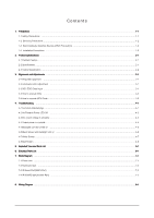
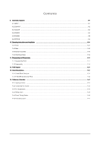
Contents 9. Schematic Diagrams ...9-1 9-1 INPUT ...9-1 9-2 DCINPUT ...9-2 9-3 SCALER ...9-3 9-4 POWER ...9-4 9-5 POWER ...9-5 9-6 KEYPAD ...9-6 10. Operating Instructions and Installation ...10-1 10-1 Front ...10-1 10-2 Rear ...10-2 10-3 Monitor Assembly ...10-3 10-4 Attaching a Base ...10-4 11. Disassembly and Reassembly ...11-1 11-1 Disassembly Block ...11-1 11-2 Reassembly ...11-4 12. PCB Diagram ...12-1 13. Circuit Descriptions ...13-1 13-1 Overall Block Structure ...13-1 13-2 IP BOARD part(Inverter Part) ...13-4 14. Reference Infomation ...14-1 14-1 Technical Terms ...14-1 14-2 Connecting the monitor ...14-3 14-3 Pin Assignments ...14-4 14-4 Timing Chart ...14-5 14-5 Preset Timing Modes ...14-6 14-6 Panel Description ...14-7
-
 1
1 -
 2
2 -
 3
3 -
 4
4 -
 5
5 -
 6
6 -
 7
7 -
 8
8 -
 9
9 -
 10
10 -
11
-
12
-
13
-
14
-
15
-
16
-
17
-
18
-
19
-
20
-
21
-
22
-
23
-
24
-
25
-
26
-
27
-
28
-
29
-
30
-
31
-
32
-
33
-
34
-
35
-
36
-
37
-
38
-
39
-
40
-
41
-
42
-
43
-
44
-
45
-
46
-
47
-
48
-
49
-
50
-
51
-
52
-
53
-
54
-
55
-
56
-
57
-
58
-
59
-
60
-
61
-
62
-
63
 |
 |

9. Schematic Diagrams
……………………………………………………………………………………………………………………………
9-1
9-1 INPUT
……………………………………………………………………………………………………………………………………… 9-1
9-2 DCINPUT
……………………………………………………………………………………………………………………………………
9-2
9-3 SCALER
……………………………………………………………………………………………………………………………………
9-3
9-4 POWER
……………………………………………………………………………………………………………………………………
9-4
9-5 POWER
……………………………………………………………………………………………………………………………………
9-5
9-6 KEYPAD
……………………………………………………………………………………………………………………………………
9-6
10. Operating Instructions and Installation
……………………………………………………………………………………………………10-1
10-1 Front
…………………………………………………………………………………………………………………………………… 10-1
10-2 Rear
………………………………………………………………………………………………………………………………………
10-2
10-3 Monitor Assembly
………………………………………………………………………………………………………………………
10-3
10-4 Attaching a Base
………………………………………………………………………………………………………………………
10-4
11. Disassembly and Reassembly
………………………………………………………………………………………………………………
11-1
11-1 Disassembly Block
…………………………………………………………………………………………………………………… 11-1
11-2 Reassembly
…………………………………………………………………………………………………………………………… 11-4
12. PCB Diagram
…………………………………………………………………………………………………………………………………
12-1
13. Circuit Descriptions
……………………………………………………………………………………………………………………………
13-1
13-1 Overall Block Structure
……………………………………………………………………………………………………………… 13-1
13-2 IP BOARD part(Inverter Part) ………………………………………………………………………………………………………… 13-4
14. Reference Infomation
……………………………………………………………………………………………………………………… 14-1
14-1 Technical Terms
……………………………………………………………………………………………………………………… 14-1
14-2 Connecting the monitor …………………………………………………………………………………………………………………14-3
14-3 Pin Assignments…………………………………………………………………………………………………………………………14-4
14-4 Timing Chart
……………………………………………………………………………………………………………………………14-5
14-5 Preset Timing Modes
………………………………………………………………………………………………………………… 14-6
14-6 Panel Description
……………………………………………………………………………………………………………………… 14-7
Contents