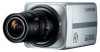
Samsung SCC-B2335 Service Manual - Page 2
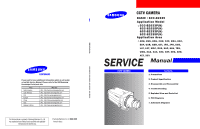
Contents
 |
UPC - 836164370037
View all Samsung SCC-B2335 manuals
Add to My Manuals
Save this manual to your list of manuals |
Page 2 highlights
CONTENTS 1. Precautions 1-1 Safety Precautions 1-2 Servicing Precautions 1-3 ESD Precautions 2. Product Specification 2-1 Product Specification 2-2 Chassis Product Specification 2-4 Option Product Specification 3. Disassembly and Reassembly 3-1 Cabinet and PCB 4. Trouble Shooting 4-1 Trouble Shooting 4-2 Alignment & Adjustment 4-2 Software Update 5. Exploded View and Parts List 5-1 Cabinet Assembly 5-2 Electrical Parts List 6. PCB Diagrams 6-1 Wiring Diagram 6-2 CCD PCB 6-3 REAR PCB 6-4 POWER 24 PCB 1-1 ~ 1-4 (1-1) (1-3) (1-4) 2-1 ~ 2-10 (2-1) (2-7) (2-9) 3-1 ~ 3-6 (3-1) 4-1 ~ 4-16 (4-2) (4-9) (4-13) 5-1 ~ 5-6 (5-2) (5-4) 6-1 ~ 6-10 (6-2) (6-4) (6-6) (6-8) CONTENTS 7. Schematic Diagrams 7-1 All block Diagram 7-2 Power Distribution Diagram 7-3 Power (Power PCB) 7-4 A1 DSP (CCD PCB) 7-5 CCD (CCD PCB) 7-6 CDS_AGC_A/D (CCD PCB) 7-7 Day_Night (CCD PCB) 7-8 EEPROM (CCD PCB) 7-9 H-Drive (CCD PCB) 7-10 I/O (CCD PCB) 7-11 IRIS Control (CCD PCB) 7-12 Motor Drive (CCD PCB) 7-13 Regulator (CCD PCB) 7-14 Reset (CCD PCB) 7-15 RS-485 (CCD PCB) 7-16 UTP (CCD PCB) 7-17 V-Drive (CCD PCB) 7-18 Video (CCD PCB) 7-19 Video Communication (CCD PCB)) 7-20 UTP 1/1 (REAR PCB) 7-21 UTP 1/2 (REAR PCB) 7-1 ~ 7-22 (7-2) (7-3) (7-4) (7-5) (7-6) (7-7) (7-8) (7-9) (7-10) (7-11) (7-12) (7-13) (7-14) (7-15) (7-16) (7-17) (7-18) (7-19) (7-20) (7-21) (7-22)
-
 1
1 -
 2
2 -
 3
3 -
 4
4 -
 5
5 -
 6
6 -
 7
7 -
 8
8 -
9
-
10
-
11
-
12
-
13
-
14
-
15
-
16
-
17
-
18
-
19
-
20
-
21
-
22
-
23
-
24
-
25
-
26
-
27
-
28
-
29
-
30
-
31
-
32
-
33
-
34
-
35
-
36
-
37
-
38
-
39
-
40
-
41
-
42
-
43
-
44
-
45
-
46
-
47
-
48
-
49
-
50
-
51
-
52
-
53
-
54
-
55
-
56
-
57
-
58
-
59
-
60
-
61
-
62
-
63
-
64
-
65
-
66
-
67
-
68
-
69
-
70
-
71
-
72
-
73
-
74
-
75
-
76
 |
 |
