Samsung TXJ2766 Service Manual - Page 18
Center Convergence Adjustment, 3-9 AGC Adjustment, 3-10 AFT VCO Adjustment
 |
View all Samsung TXJ2766 manuals
Add to My Manuals
Save this manual to your list of manuals |
Page 18 highlights
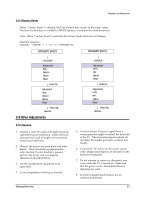
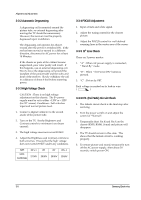
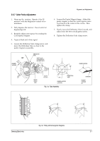
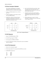
Alignment and Adjustments 3-3-8 Center Convergence Adjustment Note: Before attempting any convergence adjustment, make sure that the receiver has been powered ON for at least twenty minutes. 1. Input a crosshatch pattern from a color bar generator. 2. Adjust the Brightness and Contrast controls for a well defined pattern. 3. Adjust the two tabs of the 5-pole magnets. Change the angle between the tabs, and superimpose red and blue vertical lines in the center area of the picture screen. 4. Next, turn both tabs at the same time. Keep the angle between the tabs constant, and superimpose the red and blue horizontal lines at the center of the screen. 5. Adjust the two tabs of the 6-pole magnets. Superimpose the red/blue lines on the green. Adjusting the angle affects the horizontal lines. 6. Repeat adjustments 3, 4 and 5. The dot movement is complex because the 4-pole and 6-pole magnets interact. BLUE RED RED/BLUE GREEN BLUE RED/BLUE RED GREEN 4-Pole Magnet Movement Fig. 3-3 Center Convergence Adjustment 3-3-9 AGC Adjustment 1. Input a COLOR-BAR pattern. (CH2) 2. Set the RF input signal to 70 dBmV. 3. Use Generator for PM5518 & PM5418. 4. Set AGC (in the Factory Mode) so that the DC level of IC TDA8377 Pin 53 is 3.0±0.05V. 6-Pole Magnet Movement 3-3-10 AFT (VCO Adjustment) 1. Input an AGC adjustment signal. 2. Select Factory Mode VCO and press the MUTE key one time. 3. GEOMATRIX adjustments VS EWA VA EWP VSL EWC HS EWT 3-8 Samsung Electronics
-
 1
1 -
2
-
3
-
4
-
5
-
6
-
7
-
8
-
9
-
10
-
11
-
12
-
 13
13 -
 14
14 -
 15
15 -
 16
16 -
 17
17 -
 18
18 -
 19
19 -
 20
20 -
 21
21 -
 22
22 -
 23
23 -
24
-
25
-
26
-
27
-
28
-
29
-
30
-
31
-
32
-
33
-
34
-
35
-
36
-
37
-
38
-
39
-
40
-
41
-
42
-
43
-
44
-
45
-
46
-
47
-
48
-
49
-
50
-
51
-
52
-
53
-
54
-
55
-
56
-
57
-
58
-
59
-
60
-
61
-
62
-
63
-
64
-
65
-
66
-
67
-
68
 |
 |
