SanDisk SDCFB-128-A10 Product Manual - Page 19
Interface Description - - a10
 |
UPC - 619659015213
View all SanDisk SDCFB-128-A10 manuals
Add to My Manuals
Save this manual to your list of manuals |
Page 19 highlights
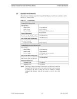
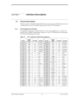
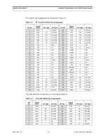
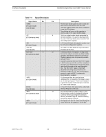
CHAPTER 3 Interface Description 3.1 Physical Description The host connects to SanDisk CompactFlash Memory cards using a standard 50-pin connector consisting of two rows of 25 female contacts each on 50 mil (1.27 mm) centers. 3.1.1 Pin Assignments and Types The signal/pin assignments are listed in Table 3-1. Low active signals have a "-" prefix. Pin types are Input, Output or Input/Output. Sections 3.3.1 and 3.3.2 define the DC characteristics for all input and output type structures.. Table 3-1 PC Card Memory Mode Pin Assignments Pin No. 1 2 3 4 5 6 7 8 9 10 11 12 13 14 15 16 17 18 19 20 21 22 23 24 25 Signal Name GND D03 D04 D05 D06 D07 -CE1 A10 -OE A09 A08 A07 VCC A06 A05 A04 A03 A02 A01 A00 D00 D01 D02 WP -CD2 Pin Type - I/O I/O I/O I/O I/O I I I I I I - I I I I I I I I/O I/O I/O O O I/O Type Ground I1Z,OZ3 I1Z,OZ3 I1Z,OZ3 I1Z,OZ3 I1Z,OZ3 I3U I1Z I3U I1Z I1Z I1Z Power I1Z I1Z I1Z I1Z I1Z I1Z I1Z I1Z,OZ3 I1Z,OZ3 I1Z,OZ3 OT3 Ground Pin No. 26 27 28 29 30 31 32 33 34 35 36 37 38 39 40 41 42 43 44 45 46 47 48 49 50 Signal Name -CD1 D11 D12 D13 D14 D15 -CE2 -VS1 -IORD -IOWR -WE RDY/BSY VCC -CSEL -VS2 RESET -WAIT -INPACK -REG BVD2 BVD1 D08 D09 D10 GND Pin Type O I/O I/O I/O I/O I/O I O I I I O - I O I O O I I/O I/O I/O I/O I/O - I/O Type Ground I1Z,OZ3 I1Z,OZ3 I1Z,OZ3 I1Z,OZ3 I1Z,OZ3 I3U Ground I3U I3U I3U OT1 Power I2Z OPEN I2Z OT1 OT1 I3U I1U,OT1 I1U,OT1 I1Z,OZ3 I1Z,OZ3 I1Z,OZ3 Ground © 2007 SanDisk Corporation 3-1 Rev. 12.0, 02/07
-
 1
1 -
2
-
3
-
4
-
5
-
6
-
7
-
8
-
9
-
10
-
11
-
12
-
13
-
 14
14 -
 15
15 -
 16
16 -
 17
17 -
 18
18 -
 19
19 -
 20
20 -
 21
21 -
 22
22 -
 23
23 -
 24
24 -
25
-
26
-
27
-
28
-
29
-
30
-
31
-
32
-
33
-
34
-
35
-
36
-
37
-
38
-
39
-
40
-
41
-
42
-
43
-
44
-
45
-
46
-
47
-
48
-
49
-
50
-
51
-
52
-
53
-
54
-
55
-
56
-
57
-
58
-
59
-
60
-
61
-
62
-
63
-
64
-
65
-
66
-
67
-
68
-
69
-
70
-
71
-
72
-
73
-
74
-
75
-
76
-
77
-
78
-
79
-
80
-
81
-
82
-
83
-
84
-
85
-
86
-
87
-
88
-
89
-
90
-
91
-
92
-
93
-
94
-
95
-
96
-
97
-
98
-
99
-
100
-
101
-
102
-
103
-
104
-
105
-
106
-
107
-
108
 |
 |