SanDisk SDCFB-128-A10 Product Manual - Page 94
SanDisk SDCFB-128-A10 - CompactFlash 128 MB Manual
 |
UPC - 619659015213
View all SanDisk SDCFB-128-A10 manuals
Add to My Manuals
Save this manual to your list of manuals |
Page 94 highlights
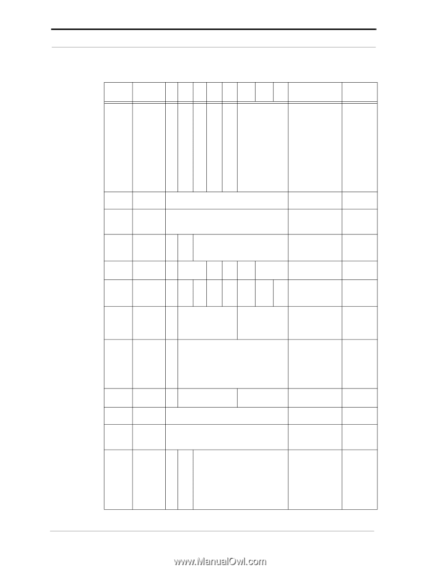
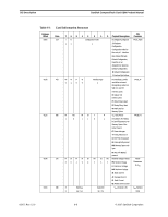
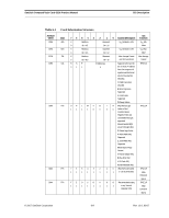
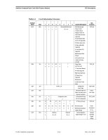
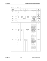
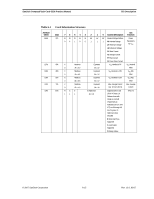
CIS Description SanDisk CompactFlash Card OEM Product Manual Table 6-1 Card Information Structure Attribute Offset 0D6h 0D8h 0DAh 0DCh 0DEh 0E0h 0E2h 0E4h 0E6h 0E8h 0EAh 0ECh Data 21h 1Bh 06h 01h 01h 21h B5h 1Eh 4Dh 1Bh 12h C2h 765 4 3 2 CIS 1 0 Content Description Function X R P RO A 0 0 1 0 0 T Power-Down TPCE_MI 1 and Twin Card. T: Twin Cards Allowed A: Audio Supported RO: Read Only Mode P: Power Down Supported R: Reserved X: More Misc Fields Bytes CISTPL_CE Configuration Entry Tuple Tuple Code Link to Next Tuple is 6 Bytes. Also limits size of this tuple to 8 bytes. Link to Next Tuple I D 0 0 Configuration Index 1 I/O Mapped Contiguous 16 3.3V Configuration TPCE_INDX M MS IR IO T P P: Power Info type TPCE_FS 0 0 0 0 0 1 R DI PI AI SI HV 0 0 1 0 0 0 LV NV PI: Peak Current 0 1 NV: Nominal Operation Supply Voltage Power Parameters for VCC X Mantissa 1 6h = 3.0 Exponent 5h = 1 Nominal Operation Supply Voltage = 3.0V Nominal Operation Supply Voltage X 1Eh 0 +.30 Nominal Operation Supply Voltage Extension Byte X Mantissa 0 9h = 4.5 Exponent 5h = 10 Max. Average Current over 10 ms is 45 mA Max. Average Current CISTPL_CE Configuration Entry Tuple Tuple Code Link to Next Tuple is 18 Bytes. Also limits size of this tuple to 20 bytes Link to Next Tuple I D 1 1 Configuration Index 2 AT Fixed Disk Primary I/O Address Configuration TPCE_INDX Configuration Index for this entry is 2. Interface Byte follows this byte. Default Configuration 02/07, Rev. 12.0 6-10 © 2007 SanDisk Corporation
-
 1
1 -
2
-
3
-
4
-
5
-
6
-
7
-
8
-
9
-
10
-
11
-
12
-
13
-
14
-
15
-
16
-
17
-
18
-
19
-
20
-
21
-
22
-
23
-
24
-
25
-
26
-
27
-
28
-
29
-
30
-
31
-
32
-
33
-
34
-
35
-
36
-
37
-
38
-
39
-
40
-
41
-
42
-
43
-
44
-
45
-
46
-
47
-
48
-
49
-
50
-
51
-
52
-
53
-
54
-
55
-
56
-
57
-
58
-
59
-
60
-
61
-
62
-
63
-
64
-
65
-
66
-
67
-
68
-
69
-
70
-
71
-
72
-
73
-
74
-
75
-
76
-
77
-
78
-
79
-
80
-
81
-
82
-
83
-
84
-
85
-
86
-
87
-
88
-
 89
89 -
 90
90 -
 91
91 -
 92
92 -
 93
93 -
 94
94 -
 95
95 -
 96
96 -
 97
97 -
 98
98 -
 99
99 -
100
-
101
-
102
-
103
-
104
-
105
-
106
-
107
-
108
 |
 |