Sanyo DP46840 Owners Manual (w/ GXEA remote) - Page 6
Getting Started - usb
 |
View all Sanyo DP46840 manuals
Add to My Manuals
Save this manual to your list of manuals |
Page 6 highlights
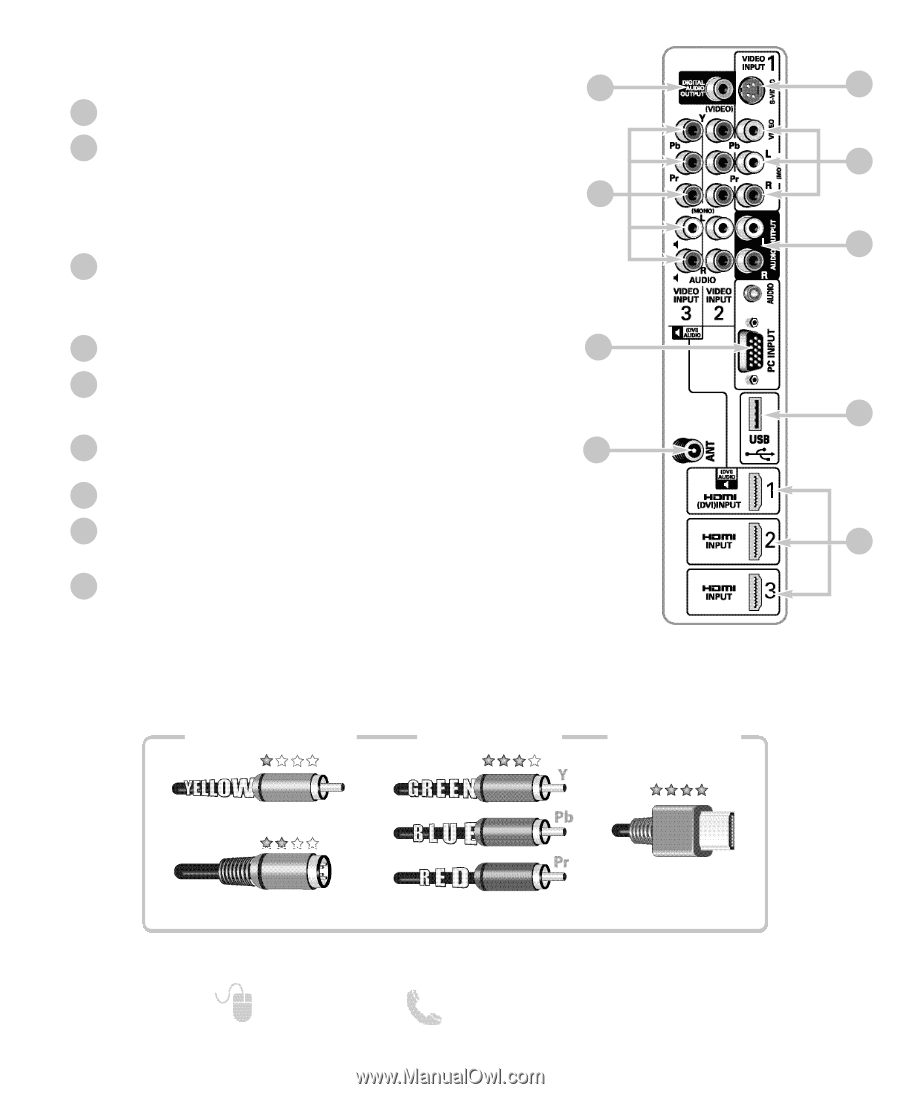
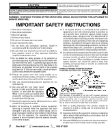
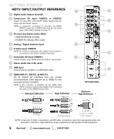
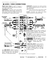
GETTING STARTED HDTV INPUT/OUTPUT REFERENCE 1 5 1 Digital Audio Output (Coaxial) 2 Component AV Input (VIDEO2 or VIDEO3) Green (Y), blue (Pb), and red (Pr) Video inputs plus the 6 white and red Audio inputs. 2 NOTE: A composite connection is possible via VIDEO INPUT2 using the Y (VIDEO) jack and the L/R audio jacks. (See Video2 Setting on page 11.) 7 3 PC Input and Stereo Audio (Mini) • MONITOR RGB (D-SUB) • AUDIO R/L (Stereo Mini Jack) 4 Analog / Digital Antenna Input 3 5 S-Video Input (VIDEO1) NOTE: An S-Video connection will replace and override a connection to the Video1 (yellow) input jack. 8 6 Composite AV Input (VIDEO1) 4 Yellow (Video), plus white and red (Audio) input jacks. 7 Stereo Audio Out (L/R) Jacks 8 USB Input View pictures stored in a USB flash drive. 9 9 HDMI (INPUT1, INPUT2, & INPUT3) An all digital AV interface that can accept uncompressed video signals up to 1080p for the very best picture possible. NOTE: A DVI conection is possible via the HDMI (DVI) INPUT1 using an appropriate adapter and connecting the audio to the VIDEO3 Audio jacks. Standard Definition High Definition HDTV BACK PANEL Optimum High Definition Composite S-Video Component H D M I (or DVI to HDMI cable/adapter) NOTE: Composite, S-Video, Component, and DVI video connections need their appropriate white and red audio connections. High Definition image available from HD signals and HD equipment. 6 Need help? www.sanyoctv.com 1-800-877-5032
-
 1
1 -
 2
2 -
 3
3 -
 4
4 -
 5
5 -
 6
6 -
 7
7 -
 8
8 -
 9
9 -
 10
10 -
 11
11 -
 12
12 -
13
-
14
-
15
-
16
-
17
-
18
-
19
-
20
-
21
-
22
-
23
-
24
-
25
-
26
-
27
-
28
-
29
-
30
-
31
-
32
-
33
-
34
-
35
-
36
-
37
-
38
-
39
-
40
-
41
-
42
-
43
-
44
-
45
-
46
-
47
-
48
-
49
-
50
-
51
-
52
 |
 |