Seagate ST3000DM001 Barracuda SATA Product Manual - Page 32
Supported ATA commands, Notes, Command name, Command code in hex, Segment, Function, Definition
 |
View all Seagate ST3000DM001 manuals
Add to My Manuals
Save this manual to your list of manuals |
Page 32 highlights
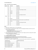
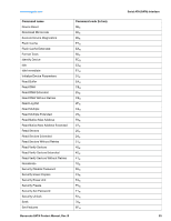
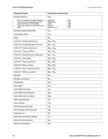
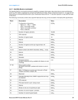
Serial ATA (SATA) Interface www.seagate.com Table 8 Serial ATA connector pin definitions Segment Pin P1 P2 P3 P4 P5 P6 P7 Power P8 P9 P10 P11 P12 P13 P14 P15 Function Definition V33 V33 V33 Ground 3.3V power 3.3V power 3.3V power, pre-charge, 2nd mate 1st mate Ground 2nd mate Ground 2nd mate V5 V5 V5 Ground 5V power, pre-charge, 2nd mate 5V power 5V power 2nd mate Ground or LED signal If grounded, drive does not use deferred spin Ground 1st mate. V12 12V power, pre-charge, 2nd mate V12 12V power V12 12V power Notes 1. All pins are in a single row, with a 1.27 mm (0.050") pitch. 2. The comments on the mating sequence apply to the case of backplane blindmate connector only. In this case, the mating sequences are: • the ground pins P4 and P12. • the pre-charge power pins and the other ground pins. • the signal pins and the rest of the power pins. 3. There are three power pins for each voltage. One pin from each voltage is used for pre-charge when installed in a blind-mate backplane configuration. • All used voltage pins (Vx) must be terminated. 4.3 Supported ATA commands The following table lists Serial ATA standard commands that the drive supports. For a detailed description of the ATA commands, refer to the Serial ATA International Organization: Serial ATA Revision 2.6 (http://www.sata-io.org). See "S.M.A.R.T. commands" on page 40 for details and subcommands used in the S.M.A.R.T. implementation. Command name Check Power Mode Device Configuration Freeze Lock Device Configuration Identify Device Configuration Restore Device Configuration Set Command code (in hex) E5H B1H / C1H B1H / C2H B1H / C0H B1H / C3H 32 Barracuda SATA Product Manual, Rev. B
-
 1
1 -
2
-
3
-
4
-
5
-
6
-
7
-
8
-
9
-
10
-
11
-
12
-
13
-
14
-
15
-
16
-
17
-
18
-
19
-
20
-
21
-
22
-
23
-
24
-
25
-
26
-
 27
27 -
 28
28 -
 29
29 -
 30
30 -
 31
31 -
 32
32 -
 33
33 -
 34
34 -
 35
35 -
 36
36 -
 37
37 -
38
-
39
-
40
-
41
-
42
-
43
-
44
-
45
-
46
-
47
-
48
 |
 |