Seagate ST3000DM001 Barracuda 7200.11 SATA Product Manual - Page 30
Drive mounting
 |
View all Seagate ST3000DM001 manuals
Add to My Manuals
Save this manual to your list of manuals |
Page 30 highlights
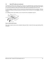
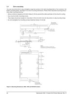
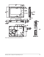
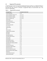
3.4 Drive mounting You can mount the drive in any orientation using four screws in the side-mounting holes or four screws in the bottom-mounting holes. See Figure 3 for drive mounting dimensions. Follow these important mounting precautions when mounting the drive: • Allow a minimum clearance of 0.030 inches (0.76 mm) around the entire perimeter of the drive for cooling. • Use only 6-32 UNC mounting screws. • The screws should be inserted no more than 0.150 inch (3.81 mm) into the bottom or side mounting holes. • Do not overtighten the mounting screws (maximum torque: 6 inch-lb). [1] 5.787 (146.9898) max. Recommended case temperature measurement location .138 (3.505) 1.122 + .020 (28.499 + .508) [1] 1.638 (41.605) [1] [1] 4.000 (101.6) 4.000 (101.60) .814 (20.676) CL of conn. Datum B 2.00 (50.80) CL of drive [1] 2 x 3.750 (2 x 95.25) .250 + .015 (6.35 + .381) (3x both sides) 1.028 max [1] (26.111 max) Notes: Dimensions are shown in inches (mm). [1] Dimensions per SFF-8301 specification 2 x 1.625 (2 x 41.28) [1] 2 (2 x x 1.750 44.45) [1] 4.000 (101.6) [1] Recommended case temperature measurement location Figure 3. Mounting dimensions (1500, 1000 and 640 GB models) 24 Barracuda 7200.11 Serial ATA Product Manual, Rev. E
-
 1
1 -
2
-
3
-
4
-
5
-
6
-
7
-
8
-
9
-
10
-
11
-
12
-
13
-
14
-
15
-
16
-
17
-
18
-
19
-
20
-
21
-
22
-
23
-
24
-
 25
25 -
 26
26 -
 27
27 -
 28
28 -
 29
29 -
 30
30 -
 31
31 -
 32
32 -
 33
33 -
 34
34 -
 35
35 -
36
-
37
-
38
-
39
-
40
-
41
-
42
-
43
-
44
-
45
-
46
-
47
-
48
-
49
-
50
 |
 |
