Sennheiser MKE 212 Instructions for Use - Page 6
Sennheiser MKE 212 Manual
 |
View all Sennheiser MKE 212 manuals
Add to My Manuals
Save this manual to your list of manuals |
Page 6 highlights
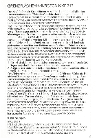
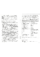
equipment with microphone input complying with DIN 45594 with microphone power supply (+ 3.5 . . . + 15 V) through pin 8. Plug wiring: see "Technical data". Length of connecting lead: approx. 3 m. Standard accessories: 1 non-crush windscreen, 1 protecting cover. MKE 212-3 With special-coupling device to fit handgrip/powering modules K 3 N, K 3 U and K 30 AV. Length of connecting lead: approx. 3 m. Standard accessories: 1 non-crush windshield, protecting cover. Tips for the use of the acoustical boundary microphone Note: Before operating the microphone the first time remove protecting cover! 1. The microphone should, if possible, be positioned or mounted on an acoustically live backing surface such as floor, wall or ceiling. Alternately, the MKE 212 can be mounted at the centre of a large wooden board of sufficient size or, if this is impossible for aesthetic reasons, on a transparent acrylic glass panel, which then is mounted on a floor stand. It can also be suspended from the ceiling. The board should be large, as its dimensions determine the point of the microphone's 6 dB accentuation. In the free field, that is without any additional surface, the MKE 212 has a lower frequency roll-off point of 1 kHz. To attain a lower cut-off frequency, e.g. 500 Hz, a board of 350 mm x 350 mm would be necessary. 2. When positioned on the floor, the microphone capsule should in any case be protected by mounting the non-crush windscreen, which is supplied as standard accessory. This windscreen does not have any influence on the acoustical characteristics of the microphone. 3. Due to its omnidirectional characteristics, the acoustical boundary microphone is of limited suitability for recordings in surroundings with a high level of background noise. Its preferred application is in recording studios and other similarly damped but good acoustical environments. 4. If you want to achieve most natural recordings, place the acoustical boundary microphone at the position in front of the instrument or the orchestra, where you have the best aural reception. 5. If two acoustical boundary microphones are used as a pair of microphones for stereo recording, the minimum distance between the two microphones should, regardless of the width of the acoustic source, be kept at approx. 1 m to obtain a defined left-right perception. 6. The advantages of this microphone become most obvious in recordings of acoustic (classical) instruments. 7. Please make sure that neither microphone nor windscreen are covered with paper, fabric, etc., as this would affect the acoustical performance of the microphone. 7 The suggestions given here are confined to the basic application of the MKE 212. We have consciously not given any finished guidelines, because from our point of view they would not be very helpful, bearing in mind that every user has his own ideas about the sound of an instrument, an orchestra or a vocal group, not to mention the ever differing acoustical conditions. The MKE 212 offers a multitude of application options, which can only be revealed by practical work and experimentation with the microphone. Ifff Frequency range Acoustic operating principe Free field transmission factor, unloaded MKE 212 R MKE 212-3 + K 3 N resp. K 3 U . . . MKE 212-3 + K 30 AV Electrical impedance MKE 212 R. . . . . . MKE 212-3 + K 3 N bzw. K 3 U . . . MKE 212-3 + K 30 AV Minimum load impedance MKE 212 R MKE 212-3 + K 3 N bzw.K 3 U . . MKE 212-3 + K 30 AV Signal-to-noise ratio ;DIN 4 5405 and CCIR 468-2) Equivalent sound pressure level Connector Plug wiring MKE 212 R Powering Current consumption Dimensions in mm (without transport case and windscreen) Weight Length of connecting lead Finish 20 Hz to 20 kHz pressure microphone 20 mV/Pa ± 2.5 dB - 54 dBV) 6.9 mV/Pa ± 2.5 dB (.4-L-- 63 c111V) 15.8 mV/Pa ± 2.5 dB( 56 dBV) approx. 1 kS2 approx. 130 12 approx. 600 12 4.7 kS2 approx. 300 12 600 12 approx. 63 dB typ. 22 dBA special coupling device for Sennheiser module system (MKE 212-3) or threaded Spin plug, DIN 45 326 (MKE 212 R), resp. pin 1 = audio pin 2 = case pin 8 = + UB 3 5 to 15 V to pin 8 (MKE 212 R) 5.6 V from Sennheiser module system or phantom powering 12 V-48 V (MKE 212-3) approx. 150 pA 185 x165 x10 approx. 850 g approx. 3 m flat black We reserve the right to alter Specifications, in particular with regard to technical improvements. Optional accessories MZA 10 Battery adapter for connection to unbalanced, medium-impedance inputs. 3-pin DIN plug. 8
-
 1
1 -
 2
2 -
 3
3 -
 4
4 -
 5
5 -
 6
6 -
 7
7 -
 8
8
 |
 |
