Sharp 20LK61M Service Manual
Sharp 20LK61M Manual
 |
View all Sharp 20LK61M manuals
Add to My Manuals
Save this manual to your list of manuals |
Sharp 20LK61M manual content summary:
- Sharp 20LK61M | Service Manual - Page 1
AND SERVICE INSTRUCTIONS 5 » CHASSIS LAYOUT ...10 » BLOCK DIAGRAM ...12 » SCHEMATIC DIAGRAMS ...14 » PRINTED WIRING BOARD ASSEMBLIES 21 » REPLACEMENT PARTS LIST ...24 » PACKING OF THE SET ...31 ELECTRICAL SPECIFICATIONS POWER INPUT 110-220 V AC 50/60 Hz POWER RATING 20LK31M 88 W 20LK61M - Sharp 20LK61M | Service Manual - Page 2
service personnel are aware of the procedures and instructions covering X-radiation. The only potential source of X-ray in current solid state TV an X-radiation problem. Every time a color chassis is serviced, the brightness high voltage circuitry. 6. When trouble shooting and taking test measurements - Sharp 20LK61M | Service Manual - Page 3
20LK31M 20LK61M IMPORTANT SERVICE SAFETY PRECAUTION (Continued) BEFORE RETURNING THE RECEIVER (Fire & Shock the factory recommended necessarily increased by using replacement replacement parts shown in this service manual, may components rated for higher voltage, wattage, etc. create shock, - Sharp 20LK61M | Service Manual - Page 4
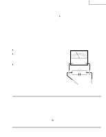
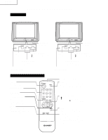
LOCATION OF USER'S CONTROL Front Panel 20LK31M LK 20LK61M LK VIDEO/AUDIOIN TERMINALS VIDEO/AUDIOIN TERMINALS POWER Press → On. Press sound. (-) Decreases sound. • In menu mode, changes or selects the TV adjustments. MUTE Press Mutes sound. Press again → Restores sound. • CLOSED CAPTION appears - Sharp 20LK61M | Service Manual - Page 5
20LK31M 20LK61M Note: INSTALLATION AND SERVICE INSTRUCTIONS (1) When performing any adjustments to resistor controls and transformers use non-metallic screwdrivers or TV alignment tools. (2) Before performing adjustments, the TV set must be on at least 15 minutes. CIRCUIT PROTECTION The receiver - Sharp 20LK61M | Service Manual - Page 6
, plug the AC cord into a wall socket. Now, the TV set is switched on and enters the service mode. To exit the service mode, turn the television off by pressing the power button. 1. Service mode. Before putting unit into the service mode, check that customer adjustments are in the normal mode. Use - Sharp 20LK61M | Service Manual - Page 7
20LK61M Below are the adjustments ranges and initial values for FIX VALUE category. FIX VALUE SERVICE SERVICE POSITION F14 F15 F16 F17 F18 F19 F20 F21 F22 F23 F24 F25 F26 ADJUST ITEM OSD CONT SHARPNESS the Vol-up/Ch-down buttons on the TV set at service mode for more than 2 seconds will - Sharp 20LK61M | Service Manual - Page 8
no noise or beat appears. Note: You have to exit the service mode first to select another channel. Video Level (TV Det Video Level) Adjustment 1. Receive a good local channel. 2. Enter the service mode signal category and select the service adjustment "S02". 3. Set the data value to "02" first, then - Sharp 20LK61M | Service Manual - Page 9
the text box position in the center. (A=B). A B Figure C. 20LK31M 20LK61M Ë MTS ADJUSTMENT MTS Level Adjustment 1. Feed the following monaural signal to rms voltmeter to pin (39) of IC3001. 3. Enter the service mode and select the service adjustment "M01". 4. Adjust the data so that the rms - Sharp 20LK61M | Service Manual - Page 10
20LK31M 20LK61M MODEL 20LK31M CHASSIS LAYOUT H PWB-B PWB-C G F PWB-A E D C B A 1 2 3 4 5 6 10 - Sharp 20LK61M | Service Manual - Page 11
MODEL 20LK61M CHASSIS LAYOUT H PWB-C G PWB-B 20LK31M 20LK61M PWB-A F E D C B A 1 2 3 4 5 6 11 - Sharp 20LK61M | Service Manual - Page 12
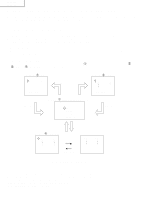
20LK31M 20LK61M MODEL 20LK31M BLOCK DIAGRAM H G F E D C B A 1 2 3 4 5 6 12 - Sharp 20LK61M | Service Manual - Page 13
MODEL 20LK61M BLOCK DIAGRAM H 20LK31M 20LK61M G F E D C B A 1 2 3 4 5 6 13 - Sharp 20LK61M | Service Manual - Page 14
20LK31M 20LK61M DESCRIPTION OF SCHEMATIC DIAGRAM NOTES: 1. The unit of resistance "ohm" is omitted. (K=kΩ=1000Ω, M=MΩ) 2. All resistors are 1/16 watt, unless otherwise noted. 3. All capacitors are µ F, unless - Sharp 20LK61M | Service Manual - Page 15
SCHEMATIC DIAGRAM: CRT and FRONT AV Unit H 20LK31M 20LK61M G F E D Ë 20LK31M C Ë 20LK61M B A 1 2 3 4 5 6 15 - Sharp 20LK61M | Service Manual - Page 16
MODEL 20LK31M SCHEMATIC DIAGRAM: MAIN Unit H 20LK31M 20LK61M G F E D C B A 1 2 3 4 5 6 7 8 9 10 11 12 16 17 - Sharp 20LK61M | Service Manual - Page 17
MODEL 20LK61M SCHEMATIC DIAGRAM: MAIN-1 Unit H 20LK31M 20LK61M G F E D C B A 1 2 3 4 5 6 7 8 9 10 11 12 18 19 - Sharp 20LK61M | Service Manual - Page 18
20LK31M 20LK61M MODEL 20LK61M SCHEMATIC DIAGRAM: MAIN-2 Unit H G F E D C B A 1 2 3 4 5 6 20 - Sharp 20LK61M | Service Manual - Page 19
PRINTED WIRING BOARD ASSEMBLIES H 20LK31M 20LK61M G F PWB-B: CRT Unit (Wiring Side) E D C PWB-C: FRONT AV Unit (Wiring Side) B A 1 2 3 4 5 6 21 - Sharp 20LK61M | Service Manual - Page 20
20LK31M 20LK61M H G F E D C B A PWB-A: MAIN Unit (Wiring Side) 1 2 3 4 5 6 22 - Sharp 20LK61M | Service Manual - Page 21
20LK31M 20LK61M H G F E D C B A PWB-A: MAIN Unit (Component Side) 1 2 3 4 5 6 23 - Sharp 20LK61M | Service Manual - Page 22
safety characteristic as the factory recommended replacement parts shown in this service manual may create shock, fire or other hazards. "HOW TO J Zener Diode, 32V AA D301 RH-EX0643GEZZ J Zener Diode, 13V AB (20LK61M) D454 RH-EX0103CEZZ J Zener Diode,5.6V AB D455 RH-DX0475CEZZ J Diode AB - Sharp 20LK61M | Service Manual - Page 23
J Diode AC å D703 RH-DX0154CEZZ J Diode AC å D704 RH-DX0154CEZZ J Diode AC D730 RH-EX0630GEZZ J Zener Diode, 9.1V AA (20LK61M) D753 RH-DX0475CEZZ J Diode (20LK61M) AB D754 RH-DX0441CEZZ J Diode AC or RH-DX0110CEZZ D755 RH-DX0441CEZZ J Diode AC or RH-DX0110CEZZ å D756 RH-DX0441CEZZ - Sharp 20LK61M | Service Manual - Page 24
250V EL. AD C759 VCKYPA2HB102K J 1000p 500V Ceramic AA C760 VCEA0A1CW107M J 100 16V EL. AC (20LK31M) C760 VCEA0A1CW228M J 2200 16V EL. AD (20LK61M) C761 VCQYTA1HM333K J 0.033 50V Mylar AA C771 VCEA0A1CW476M J 47 16V EL. AB C772 VCEA0A1CW107M J 100 16V EL. AC C801 VCCCCY1HH160J J 16p - Sharp 20LK61M | Service Manual - Page 25
8W Carbon AB R902 VRS-CY1JF750J J 75 1/16W M-Ox. AA R905 VRS-CY1JF102J J 1.0k 1/16W M-Ox. AA (20LK61M) R906 VRS-CY1JF102J J 1.0k 1/16W M-Ox. AA R924 VRS-CY1JF104J J 100k 1/16W M-Ox. AA (20LK61M) R925 VRS-CY1JF104J J 100k 1/16W M-Ox. AA R961 VRS-CY1JF101J J 100 1/16W M-Ox. AA R962 VRS - Sharp 20LK61M | Service Manual - Page 26
QFSHD1013CEZZ J Fuse Holder AC FH702 QFSHD1014CEZZ J Fuse Holder AC P302 QPLGN0461CEZZ J Plug, 4-pin (S)(20LK31M) AB P303 QPLGN0461CEZZ J Plug, 4-pin (S)(20LK61M) AB P401 QPLGN0561CEZZ J Plug, 5-pin (GBN) AB Ref. No. Part No. 5 Description Code P601 QPLGN0660CEZZ J Plug, 6-pin (K) AC - Sharp 20LK61M | Service Manual - Page 27
P852 QPLGN0461CEZZ J Plug, 4-pin (YBN) AB SC851 QSOCV0840CEZZ J CRT Socket AK 20LK31M 20LK61M Ref. No. Part No. 5 Description Code PWB-C: DUNTKA222WEV0 (20LK31M) PWB-C: DUNTKA222WEV2 (20LK61M) FRONT AV UNIT MISCELLANEOUS PARTS J1001 QJAKE0150CEZZ J Jack, Video IN AD J1002 QJAKE0185CEZZ - Sharp 20LK61M | Service Manual - Page 28
Cabinet Ass'y BA (20LK61M) 1-1 Not Available - Front Cabinet - 1-2 GCOVA0002GJSA X Cover for R/C AL 1-3 HBDGB0019PESB R Badge, "SHARP" AD 1-4 JBTN- J Antenna Adapter AM TiNS-7056GJZZ X Operation Manual (20LK31M) AL TiNS-7057GJZZ X Operation Manual (20LK61M) AL 1-3 1-2 1-4 30 - Sharp 20LK61M | Service Manual - Page 29
20LK31M 20LK61M Ref. No. Part No. 5 PACKING OF THE SET Description Code Ref. No. Part No. 5 Description Code 5 Polyethylene Bag 5 Polyethylene Foam Wrap Operation Manual Infrared R/C Unit Rod Antenna Antenna Adapter 5 Batteries 5 Buffer Material FRONT 5 Packing Case 5 MARK : Not - Sharp 20LK61M | Service Manual - Page 30
20LK31M 20LK61M Ref. No. Part No. 5 Description Code Ref. No. Part No. 5 Description Code COPYRIGHT © 2000 BY SHARP CORPORATION ALL RIGHTS RESERVED. No part of this publication may be reproduced, stored in a retrieval system, or transmitted in any form or by any means, electronic,
-
 1
1 -
 2
2 -
 3
3 -
 4
4 -
 5
5 -
 6
6 -
 7
7 -
8
-
9
-
10
-
11
-
12
-
13
-
14
-
15
-
16
-
17
-
18
-
19
-
20
-
21
-
22
-
23
-
24
-
25
-
26
-
27
-
28
-
29
-
30
 |
 |
20LK31M
20LK61M
COLOR TELEVISION
Chassis No. SN-70A
In the interests of user-safety (Required by safety regulations in some countries) the set should be restored to its
original condition and only parts identical to those specified should be used.
S80G420LK31M/
»
ELECTRICAL SPECIFICATIONS
.........................................................................................................
1
»
IMPORTANT SERVICE SAFETY PRECAUTION
................................................................................
2
»
LOCATION OF USER'S CONTROL
.....................................................................................................
4
»
INSTALLATION AND SERVICE INSTRUCTIONS
...............................................................................
5
»
CHASSIS LAYOUT
.............................................................................................................................
10
»
BLOCK DIAGRAM
..............................................................................................................................
12
»
SCHEMATIC DIAGRAMS
...................................................................................................................
14
»
PRINTED WIRING BOARD ASSEMBLIES
........................................................................................
21
»
REPLACEMENT PARTS LIST
...........................................................................................................
24
»
PACKING OF THE SET
......................................................................................................................
31
Page
CONTENTS
ELECTRICAL SPECIFICATIONS
Specifications are subject to change without
prior notice.
SERVICE MANUAL
20LK31M
20LK61M
SHARP CORPORATION
MODELS
20LK61M
20LK31M
POWER INPUT
........................................
110-220 V AC 50/60 Hz
POWER RATING
20LK31M
............................................................................
88 W
20LK61M
............................................................................
98 W
PICTURE SIZE
..........................................
1,194cm
2
(185sq inch)
CONVERGENCE
............................................................
Magnetic
SWEEP DEFLECTION
....................................................
Magnetic
FOCUS
..............................................
Hi-Bi-Potential Electrostatic
INTERMEDIATE FREQUENCIES
Picture IF Carrier Frequency
....................................
45.75 MHz
Sound IF Carrier Frequency
.....................................
41.25 MHz
Color Sub-Carrier Frequency
...................................
42.17 MHz
(Nominal)
AUDIO POWER
OUTPUT RATING
20LK31M
...........................................
1.5W (at 10% distortion)
20LK61M
...........................................
3.0W (at 10% distortion)
SPEAKER
SIZE
........................................................................
9 cm
×
5 cm
VOICE COIL IMPEDANCE
20LK31M
...................................................
16 ohm at 400 Hz
20LK61M
...................................................
32 ohm at 400 Hz
ANTENNA INPUT IMPEDANCE
VHF/UHF
...................................................
75 ohm Unbalanced
TUNING RANGES
VHF-Channels
.............................................................
2 thru 13
UHF-Channels
...........................................................
14 thru 69
CATV Channels
.........................................................
1 thru 125
LK
LK