Sharp 20LK61M Service Manual - Page 7
Fix Value, Signal
 |
View all Sharp 20LK61M manuals
Add to My Manuals
Save this manual to your list of manuals |
Page 7 highlights
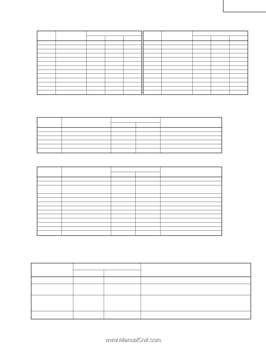
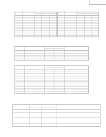
20LK31M 20LK61M Below are the adjustments ranges and initial values for FIX VALUE category. FIX VALUE SERVICE POSITION F01 F02 F03 F04 F05 F06 F07 F08 F09 F10 F11 F12 F13 ADJUST ITEM OPTION 1 OPTION 2 E-SAVE TUNER SETUP R-TONE RD R-TONE BD B-TONE RD B-TONE BD FM LEVEL AFC GAIN G DRIVE FBT BLK SW V COMP RANGE 00-FF 00-FF 00-3F 00, 01 00-7F 00-7F 00-7F 00-7F 00-1F 00, 01 00, 0F 00,01 00-07 DATA INITIAL VALUE B0 04 23 00 19 00 00 12 0C 00 00 01 07 (Hex) A0 0C 1F 00 03 7C 00 04 0C 00 0F 01 07 SERVICE POSITION F14 F15 F16 F17 F18 F19 F20 F21 F22 F23 F24 F25 F26 ADJUST ITEM OSD CONT SHARPNESS FLT SYS KILLER OP PRE SHOOT CORING DC REST BS START BS GAIN ABL START R/B ANGLE H BLK R H BLK L RANGE 00-03 00-3F 00-07 00-07 00-03 00-03 00-03 00-03 00-03 00-07 00-0F 00-0F 00-0F DATA INITIAL VALUE 02 19 00 04 03 04 02 01 01 00 08 04 04 Table - A Below are the ranges and initial values for each adjustment and in each categories. DEF SERVICE POSITION D01 D02 D03 D04 D05 D06 ADJUST ITEM H-PHASE V-SIZE V-POSITION CC-POSITION V-LINEARITY V-S-CORRECTION DATA RANGE INITIAL VALUE 00-1F 0C 00-7F 40 00-3F 20 00-FF 1A 00-1F 10 00-1F 10 ADJUSTMENT CONTENTS Must be "20" Must be "12" Must be "0F" SIGNAL Table - B SERVICE POSITION S01 S02 S03 S04 S05 S06 S07 S08 S09 S10 S11 S12 S13 ADJUST ITEM RF AGC VIDEO LEVEL Y-MUTE SUB BIAS R-BIAS G-BIAS B-BIAS R-DRIVE B-DRIVE CONTRAST TINT COLOR BRIGHTNESS DATA RANGE INITIAL VALUE 00-3F 14 00-07 03 00-03 00 00-FF 40 00-FF 00 00-FF 00 00-7F 00 00-7F 40 00-7F 40 00-7F 5A 00-7F 40 00-7F 40 00-7F 40 ADJUSTMENT CONTENTS "01":Y-MUTE, "02":V-STOP&Y-MUTE "03":Activate color killer circuit Must be "30" Note: Refer to the SERVICE ADJUSTMENT for each corresponding values. Table - C (Hex) 01 19 00 02 00 04 02 01 01 00 08 03 06 Holding down both the Vol-up/Ch-down buttons on the TV set at service mode for more than 2 seconds will automatically write the above initial values into IC2101. PART REPLACED IC2001 IC201 IC2101 ADJUSTMENT NECESSARY UNNECESSARY X X X NOTES Data is stored in IC2101. The adjustment is needed to compensate for characteristics of parts including IC201. Holding down both the Vol-up/Ch-down buttons on the TV set in the service mode for more than 2 seconds will automatically write the above initial values into IC2101. CRT X Adjust items related to picture tube only. Table - D 7
-
 1
1 -
 2
2 -
 3
3 -
 4
4 -
 5
5 -
 6
6 -
 7
7 -
 8
8 -
 9
9 -
 10
10 -
 11
11 -
 12
12 -
13
-
14
-
15
-
16
-
17
-
18
-
19
-
20
-
21
-
22
-
23
-
24
-
25
-
26
-
27
-
28
-
29
-
30
 |
 |