Sharp 20LK61M Service Manual - Page 9
Mts Adjustment
 |
View all Sharp 20LK61M manuals
Add to My Manuals
Save this manual to your list of manuals |
Page 9 highlights
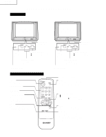
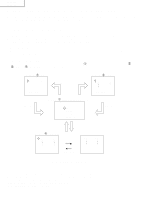
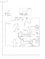
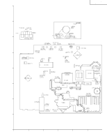
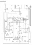
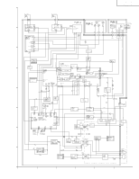
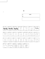
Vertical-Size, V-Linearity and V-S Correction Adjustments 1. Receive a good local channel. 2. Enter the service mode DEF category and select the adjustment "D02" for Vertical Size, "D05" for VLinearity and "D06" for V-S Correction Adjustment. 3. Set in order "D05" for V-Linearity, "D06" for V-S Correction and set the data to get the best linearity. 4. Then adjust "D02" data unitl it become a proper vertical size. Horizontal Position Adjustment 1. Receive a good local channel. 2. Enter the service mode DEF category and select the adjustment "D01". 3. Adjust "D01" data value to center the picture. Vertical-Phase Adjustment 1. Receive a good local channel. 2. Enter the service mode DEF category and select the adjustment "D03". 3. Adjust "D03" bus data to get the most acceptable vertical position. Note: The step range is 20 (032) ±10 steps. Caption Position Adjustment (Horizontal) 1. Receive a good local channel. 2. Enter the service mode DEF category and select the adjustment "D04". 3. A black text box will appear on the screen. (see Figure C. below) 4. Adjust "D04" data value to balance the text box position in the center. (A=B). A B Figure C. 20LK31M 20LK61M Ë MTS ADJUSTMENT MTS Level Adjustment 1. Feed the following monaural signal to pin (14) of IC3001. Monaural signal: 300Hz, 245mVrms 2. Connect the rms voltmeter to pin (39) of IC3001. 3. Enter the service mode and select the service adjustment "M01". 4. Adjust the data so that the rms voltmeter reads 490 ±10mVrms. MTS VCO Adjustment 1. Keep the unit in no-signal state. 2. Connect the frequency counter to pin (39) of IC3001. 3. Connect a capacitor (100µF, 50V) in between positive(+) side of C3005 and ground. 4. Enter the service mode and select the service adjustment "M02" 5. Adjust the data so that the frequency counter reads 62.94 ±0.75kHz. Filter Adjustment 1. Feed the following stereo pilot signal to pin (14) of IC3001 . Stereo pilot signal: 9.4kHz, 600mVrms. 2. Enter the service mode and select the service adjustment "M03". 3. Adjust the data at the point where "OK" appears on the screen. The "OK" represents the approximate center of the adjustable range of the data. Separation Adjustment 1. Connect the rms voltmeter to pin (39) of IC3001. 2. Receive the following composite stereo signal 1. Composite stereo signal: 30% modulation, left channel only, noise reduction on, 300Hz 3. Enter the service mode and select the service adjustment "M04". 4. Adjust the data until the AC voltage reading of the rms voltmeter is minimum. 5. Receive the following composite stereo signal 2. Stereo signal: 30% modulation, left channel only, noise reduction on, 3kHz 6. Enter the service mode and select the service adjustment "M05". 7. Adjust the data until the AC voltage reading of the rms voltmeter is minimum. 8. Take the above steps 1 thru 7 again for fine adjustment. 9
-
 1
1 -
2
-
3
-
 4
4 -
 5
5 -
 6
6 -
 7
7 -
 8
8 -
 9
9 -
 10
10 -
 11
11 -
 12
12 -
 13
13 -
 14
14 -
15
-
16
-
17
-
18
-
19
-
20
-
21
-
22
-
23
-
24
-
25
-
26
-
27
-
28
-
29
-
30
 |
 |
