Sharp 37D6U Service Manual
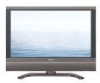
Sharp 37D6U - LC - 37" LCD TV Manual
 |
UPC - 074000362987
View all Sharp 37D6U manuals
Add to My Manuals
Save this manual to your list of manuals |
Sharp 37D6U manual content summary:
- Sharp 37D6U | Service Manual - Page 1
LC-26D6U LC-32D6U LC-37D6U SERVICE MANUAL S95N8LC-37D6U LCD COLOR TELEVISION LC-26D6U LC-32D6U MODELS LC-37D6U In the interests of user-safety (Required by safety regulations in some countries) the set should be restored to its original condition and only parts identical to those specified should be - Sharp 37D6U | Service Manual - Page 2
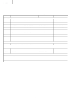
LC-26D6U LC-32D6U LC-37D6U LIST OF CHANGED PARTS Ref.No. Description PWB ASSEMBLIES DIGITAL Unit AV Unit KEY Unit R/C, LED Unit MAIN Unit SP(L) Terminal Unit SP(R) Terminal Unit POWER Unit LC-26D4U → LC-26D6U LC-26D4U LC-26D6U DUNTKD331FE12 DUNTKD352DE17 DUNTKD353DE17 DUNTKD354DE17 - Sharp 37D6U | Service Manual - Page 3
LC-26D6U LC-32D6U LC-37D6U LIST OF CHANGED PARTS Ref.No. Description PWB ASSEMBLIES DIGITAL Unit AV Unit KEY Unit R/C, LED Unit MAIN Unit SP(L) Terminal Unit SP(R) Terminal Unit POWER Unit LC-32D4U → LC-32D6U LC-32D4U LC-32D6U DUNTKD331FE13 DUNTKD352DE18 DUNTKD353DE18 DUNTKD354DE18 - Sharp 37D6U | Service Manual - Page 4
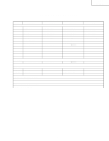
LC-37D6U DUNTKD331FE14 DUNTKD352DE19 DUNTKD353DE19 DUNTKD354DE19 DUNTKD376FE06 RDENCA140WJQZ DUNTKD331FE11 DUNTKD352WE06 DUNTKD353WE01 DUNTKD354WE02 DUNTKD376FM03 DUNTKD355WE01 DUNTKD356WE01 Note No parts changed No parts changed No parts changed No parts changed Some parts changed LCD - Sharp 37D6U | Service Manual - Page 5
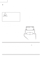
replacement parts which do not rated for higher voltage, wattage, etc. have the same safety characteristics as the factory Replacement parts which have these special safety recommended replacement parts shown in this service characteristics are identified in this manual; electrical manual - Sharp 37D6U | Service Manual - Page 6
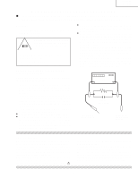
coffret métallique, tête des vis, arbres de commande et des boutons, écusson, etc.) et mesurer LC-26D6U:F701, F702 (3.15A, 250V) la chute de tension CA en-travers de la résistance. LC-32D6U/LC-37D6U: F701, F702 (5A, 250V) F703 (1A, AC250V), F704 (117°C, 2A) Toutes les vérifications doivent être - Sharp 37D6U | Service Manual - Page 7
LC-26D6U LC-32D6U LC-37D6U Precautions for using lead-free solder 1 Employing lead-free solder "PWBs" of this model employs lead-free solder. The LF symbol indicates lead-free solder, and is attached on the PWBs and service manuals. The alphabetical character following LF shows the type of lead-free - Sharp 37D6U | Service Manual - Page 8
LC-26D6U LC-32D6U LC-37D6U SPECIFICATIONS Item LCD panel Number of dots TV Function TV-standard (CCIR) Receiving VHF/UHF Channel CATV Digital Terrestrial Broadcast (8VSB) Digital cable (64/256 QAM) Model: LC-37D6U Model: LC-32D6U 37" Advanced Super 32" Advanced Super View & BLACK TFT LCD - Sharp 37D6U | Service Manual - Page 9
Surround resets to off Image position initializes ** Press SYSTEM RESET if the TV does not operate after starting up. NOTE Pressing RESET will not work if the TV is in standby mode. Pressing RESET will not delete channel preset or secret number. OPERATION MANUAL LC-26D6U LC-32D6U LC-37D6U - Sharp 37D6U | Service Manual - Page 10
LC-26D6U LC-32D6U LC-37D6U 10 Part names Remote control unit 1 16 2 3 4 5 6 7 8 9 10 11 12 13 14 15 1 TV POWER: Switches the Liquid Crystal Television VOL / : Sets the volume. 9 SURROUND: Selects Surround settings. 18 10 INFO: Displays the program information screen. 11 FREEZE: Sets the - Sharp 37D6U | Service Manual - Page 11
audio signal to AUDIO terminal of INPUT4. HDMI cable (commercially available) HDMI equipment Displaying an image from HDMI equipment 1 To watch an HDMI equipment image, select "INPUT4" from "INPUT SOURCE" menu 5 Press / to select the desired item and press ENTER. using INPUT on the remote - Sharp 37D6U | Service Manual - Page 12
qualified service professional about using an optional bracket to mount the TV to the wall. Carefully read the instructions that come with the bracket before beginning work. Hanging on the wall Wall mount bracket. (See the bracket instructions for details.) About setting the TV angle LC-37D6U LC - Sharp 37D6U | Service Manual - Page 13
LC-26D6U LC-32D6U LC-37D6U 13 Appendix RS-232C port specifications PC Control of the TV When a program is set, the TV can be controlled from the PC using the RS-232C terminal. The input signal (PC/AV) can be selected, the volume Any numerical value can replace the "x" on the 0DH) Problem response - Sharp 37D6U | Service Manual - Page 14
LC-37D6U 14 Basic adjustment settings Menu items List of menu items to help you with operations Picture OPC Backlight Contrast Brightness Color Tint Sharpness Advanced Color Temp. Black 3D-Y/C Monochrome Film Mode Audio Treble Bass Balance Surround Option Audio Only Digital Noise Reduction HDMI - Sharp 37D6U | Service Manual - Page 15
LC-26D6U DIMENSIONS (LC-26D6U) LC-26D6U LC-32D6U LC-37D6U Unit: inch/(mm) 223/64 (560) 2617/32 (674) 2223/64 (567.9) 67/64 (155) 223/64 (60) 41/4 (108) 125/8 (320.6) 149/64 (359.2) - Sharp 37D6U | Service Manual - Page 16
LC-26D6U LC-32D6U LC-37D6U LC-32D6U DIMENSIONS (LC-32D6U) Unit: inch/(mm) 2427/32 (631) 3149/64 (807) 2737/64 (700.4) 349/64 (96) 41/4 (108) 1535/64 (395.1) 16 (406.5) 2521/32 (652) 237/32 (590) 1913/32 (493) 27/16 (62) 77/8 (200) 431/64 (114) 113/8 (289) 77/8 (200) 433/64 (115) 16 - Sharp 37D6U | Service Manual - Page 17
LC-37D6U DIMENSIONS (LC-37D6U) LC-26D6U LC-32D6U LC-37D6U Unit: inch/(mm) 2613/32 (671) 3637/64 (929) 323/8 (822.6) 43/8 (111) 41/4 (108) 181/4 (463.8) 1723/64 (440.8) 2811/32 (720) 2515/16 (659) 221/8 (562) 77/8 (200) 431/64 (114) 123/64 (306) 213/32 (61) 77/8 (200) 43/32 (104) 17 - Sharp 37D6U | Service Manual - Page 18
LC-26D6U LC-32D6U LC-37D6U REMOVING OF MAJOR PARTS 1. Remove the AC Cover and Jack Cover 1. 2. Detach the SD Card Cover and PC Card Cover 2. 3. Remove the 1 lock screw 3 and detach the Bracket Cover (LC-32/37D6U only). 4. Remove the 4 lock screws 4 and detach the Stand. 5. Remove the SP Wire (L) and - Sharp 37D6U | Service Manual - Page 19
Control Shield q. 9. Remove the 5 lock screws w and detach the Main Shield A. 10 Center Angle 10 LC-26D6U LC-32D6U LC-37D6U 12 Main Shield A 11 LC-32/37D6U LC-26D6U LCD Control Shield 10. Remove the connectors,(P5703,P3103,P1105,P2501,P3005,P3101,CN1,CN2,CN801,CN802,CN803, CN804,CN805,CN7502 - Sharp 37D6U | Service Manual - Page 20
LC-26D6U LC-32D6U LC-37D6U 11. Remove the 4 lock screws e and FFC. Detach the Main Shield 16. Remove the 6 lock screws a and detach the Power PWB. 17. Remove the 4 lock screws s and detach the LCD Control PWB. 18. Remove the KEY PWB. 18-1. Remove the 2 lock screws d from the Top Control Cover. 18-2. - Sharp 37D6U | Service Manual - Page 21
2 lock screws 31 and detach the LCD Panel Module. LC-26D6U LC-32D6U LC-37D6U 31 LC-26D6U 31 31 31 LC-32/37D6U Speaker Bracket (R) SP (R) PWB 25 26 26 R/C, LED PWB 29 LC-32/37D6U LCD Panel Module 28 28 Speaker Bracket (L) SP (L) PWB 27 Speaker Braket (R) SP (R) PWB 26 25 R/C, LED - Sharp 37D6U | Service Manual - Page 22
LC-26D6U LC-32D6U LC-37D6U OVERALL WIRING DIAGRAM J LC-26D6U LC-32D6U LC-37D6U I H G F E D C B A 1 2 3 4 5 6 7 8 9 10 11 12 13 14 15 16 17 18 19 22 23 - Sharp 37D6U | Service Manual - Page 23
LC-26D6U LC-32D6U LC-37D6U DESCRIPTION OF SCHEMATIC DIAGRAM VOLTAGE MEASUREMENT CONDITION: 1. The voltages at test points are measured on exclusive AC adaptor and the stable supply voltage of AC 120V. Signals are fed by a color bar signal generator for servicing OUTLET BEFORE REPLACING PARTS. 2. - Sharp 37D6U | Service Manual - Page 24
SCHEMATIC DIAGRAM Ë SP(L) Terminal Unit H LC-26D6U LC-32D6U LC-37D6U G F E Ë SP(R) Terminal Unit D C B A 1 2 3 4 5 6 25 - Sharp 37D6U | Service Manual - Page 25
J203 J202 LC-26D6U LC-32D6U LC-37D6U PRINTED WIRING BOARD ASSEMBLIES H 1 LUG204 G SP(L) Terminal Unit (Component Parts Side-A) P204 SP(L) Terminal Unit (Chip Parts Side-A) F E SP(L) Terminal Unit (Component Parts Side-B) TL212 TL210 TL211 C211 D208 C210 FB207 FB208 C212 D207 TL208 TL209 SP - Sharp 37D6U | Service Manual - Page 26
1. NUMERO DU MODELE 2. NO. DE REF 3. NO. DE PIECE 4. DESCRIPTION in CANADA: Contact SHARP Electronics of Canada Limited Phone (416) 890-2100 Ref. No. Part No. 5 Description Code LC-32D6U RLCUCA025WJZZ J 32 WIDE LCD PANEL MODULE Unit DZ LC-37D6U RLCUCA026WJZZ J 37 WIDE LCD PANEL MODULE Unit - Sharp 37D6U | Service Manual - Page 27
LC-26D6U LC-32D6U LC-37D6U Ref. No. Part No. 5 Description Code CABINET AND MECHANICAL PARTS (LC-26D6U) 1 CCABAB084WJ01 X Front Cabinet Ass'y BE 1-1 Not Available - Front Cabinet - 1-2 Not Available - Badge, SHARP - 1-3 PSPAHA323WJZZ X Mask Spacer, x2 AC 1-4 PSPAHA324WJZZ X Mask - Sharp 37D6U | Service Manual - Page 28
CABINET AND MECHANICAL PARTS (LC-26D6U) 74 LC-26D6U LC-32D6U LC-37D6U H 3-1 3-2 3-3 3 3-4 75 57 66-1 E 67 66 67 10 H 95 M G 60 74 7 C K 96 F 87 33 75 47 E 66-2 O PG A D 37 83 V 1-3 6 1-4 F J 54 1-4 34 74 6-1 5 5-2 5-1 6-2 1-5 1-3 24 11 72 68 25 76 - Sharp 37D6U | Service Manual - Page 29
LC-26D6U LC-32D6U LC-37D6U Ref. No. Part No. 5 Description Code CABINET AND MECHANICAL PARTS (LC-32D6U) 1 CCABAB085WJ01 X Front Cabinet Ass'y BL 1-1 Not Available - Front Cabinet - 1-2 Not Available - Badge, SHARP Model HDMI) AA X Screw, x1 (FOR Stand-Cover) AB X Screw, x4 (FOR Stand - Sharp 37D6U | Service Manual - Page 30
CABINET AND MECHANICAL PARTS (LC-32D6U) LC-26D6U LC-32D6U LC-37D6U H G A 1-3 1-4 F 1-3 1-5 71 3-1 3-2 10 74 74 3-3 3 3-4 7 57 K 64 E 64-2 M 61 56 F Q R 27 70 62 U 45 47 70 44 85 T 96 S 51 70 78 70 37 D 83 93 90 70 38 K 46 53 94 98 8 52 T 22 23 S 70 35 N 18 43 - Sharp 37D6U | Service Manual - Page 31
LC-26D6U LC-32D6U LC-37D6U Ref. No. Part No. 5 Description Code CABINET AND MECHANICAL PARTS (LC-37D6U) 1 CCABAB086WJ01 X Front Cabinet Ass'y BP 1-1 Not Available - Front Cabinet - 1-2 Not Available - Badge, SHARP - 1-3 PSPAHA412WJZZ X Mask Spacer, x2 AD 1-4 PSPAHA416WJZZ X Mask - Sharp 37D6U | Service Manual - Page 32
CABINET AND MECHANICAL PARTS (LC-37D6U) LC-26D6U LC-32D6U LC-37D6U 83 H 94 90 3-1 72 27 E 83-2 90 3-2 3-3 3 94 M 3-4 H 44 32 E G A 1-3 1-4 78 U 61 89 39 60 T 64 S 41 33 31 89 51 88 I 4-1-3 C 13 D 27 37 55 79 M 89 F 52 K 62 63 80 8 21 22 66 89 67 T S 89 46 4-1-2 - Sharp 37D6U | Service Manual - Page 33
LC-26D6U LC-32D6U LC-37D6U Ref. No. Part No. 5 Description Code SUPPLIED ACCESSORIES å X1 QACCDA039WJPZ X Ac Cord AR X2 RRMCGA415WJSA X Remote Control Unit BA X3 LHLDW0110CESD X Cable Clamp AF X4 LHLDWA083WJ00 X Cable Band AE X5 TiNS-B947WJZZ X Operation Manual AY X6 - Sharp 37D6U | Service Manual - Page 34
PACKING OF THE SET 5S6 X1 X2 X3 X4 X5 5S6 X6 X7 5S5 5S2 LC-26D6U LC-32D6U LC-37D6U 5S4 5S6 5S6 5S3 5S7 5S1 35 5 Not Replacement item - Sharp 37D6U | Service Manual - Page 35
LC-26D6U LC-32D6U LC-37D6U COPYRIGHT © 2005 BY SHARP CORPORATION ALL RIGHTS RESERVED. No part of this publication may be reproduced, stored in a retrieval system, or transmitted in any form or by any means, electronic, mechanical, photocopying, recording, or otherwise, without prior written
-
 1
1 -
 2
2 -
 3
3 -
 4
4 -
 5
5 -
 6
6 -
 7
7 -
8
-
9
-
10
-
11
-
12
-
13
-
14
-
15
-
16
-
17
-
18
-
19
-
20
-
21
-
22
-
23
-
24
-
25
-
26
-
27
-
28
-
29
-
30
-
31
-
32
-
33
-
34
-
35
 |
 |
LC-26D6U
LC-32D6U
LC-37D6U
SERVICE MANUAL
LCD COLOR TELEVISION
MODELS
LC-26D6U
LC-32D6U
LC-37D6U
In the interests of user-safety (Required by safety regulations in some countries) the set should be restored
to its original condition and only parts identical to those specified should be used.
CONTENTS
Page
»
LIST OF CHANGED PARTS
...........................................................................................................................
2
»
IMPORTANT SERVICE SAFETY PRECAUTION
........................................................................................
5
»
SPECIFICATIONS
........................................................................................................................................
8
»
OPERATION MANUAL
................................................................................................................................
9
»
DIMENSIONS
............................................................................................................................................
15
»
REMOVING OF MAJOR PARTS
................................................................................................................
18
»
OVERALL WIRING DIAGRAM
...................................................................................................................
22
»
DESCRIPTION OF SCHEMATIC DIAGRAM
.............................................................................................
24
»
SCHEMATIC DIAGRAM
.............................................................................................................................
25
»
PRINTED WIRING BOARD ASSEMBLIES
................................................................................................
26
»
PARTS LIST
...............................................................................................................................................
27
»
PACKING OF THE SET
.............................................................................................................................
35
OUTLINE
This model is based on the LC-26/32/37D4U and is equipped with a redesigned speaker. This Service Manual
covers the modifications alone. For the other points, refer to the LC-26/32/37D4U Service Manual.
S95N8LC-37D6U
SHARP CORPORATION
This document has been published to be used for
after sales service only.
The contents are subject to change without notice.