Sharp KB-4425J Installation Manual
Sharp KB-4425J Manual
 |
View all Sharp KB-4425J manuals
Add to My Manuals
Save this manual to your list of manuals |
Sharp KB-4425J manual content summary:
- Sharp KB-4425J | Installation Manual - Page 1
MICROWAVE DRAWER 30" Slide-in Range INSTALLATION MANUAL SPECIAL WARNING INSTALLATION AND SERVICE MUST BE PERFORMED BY A QUALIFIED INSTALLER. IMPORTANT: SAVE THIS INSTALLATION MANUAL FOR LOCAL ELECTRICAL INSPECTOR'S USE. READ AND SAVE THESE INSTRUCTIONS FOR FUTURE REFERENCE. CLEARANCES & DIMENSIONS - Sharp KB-4425J | Installation Manual - Page 2
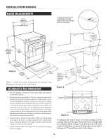
INSTALLATION MANUAL RANGE MEASUREMENTS 31 1/4" glass and control panel 29 7/8" width of unit 36 is smooth and flat and that it adheres to the sub-floor solidly. • Check location where the range will be installed for proper electrical supply. 6" 6 1/8" Maximum depth of cord, plug and 7 3/8" - Sharp KB-4425J | Installation Manual - Page 3
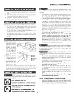
Drawer and contact your dealer or a SHARP AUTHORIZED SERVICER. IMPORTANT SAFETY INSTRUCTIONS If the information in this manual is not followed exactly, a fire or electrical shock may result causing property damage, personal injury or death. • ALL RANGES CAN TIP • INJURY TO PERSONS COULD - Sharp KB-4425J | Installation Manual - Page 4
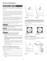
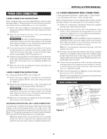
range connection opening should be 1 3/8-inches. Risk of fire or electrical shock exists if an incorrect size range cord kit is used or the Installation Manual shock. 208/240 VOLT CONNECTION INSTRUCTIONS The range can be set for 208V or 240V. The voltage setting for your range is pre-set at 240V from - Sharp KB-4425J | Installation Manual - Page 5
cover. See Figure 7. GROUNDING INSTRUCTIONS- ONLY 3-WIRE CONNECTIONS: A ground strap is installed on this range which connects the center terminal of the separate ground screw attached to the range chassis and to an adequate ground source. INSTALLATION MANUAL 3 & 4-WIRE PERMANENT WIRE CONNECTIONS 3- - Sharp KB-4425J | Installation Manual - Page 6
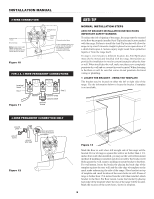
INSTALLATION MANUAL 3-WIRE CONNECTION Connect line 1 here. Ground strap Note: Install strain relief clamp -TIP NORMAL INSTALLATION STEPS ANTI-TIP BRACKET INSTALLATION INSTRUCTIONS IMPORTANT SAFETY WARNING To reduce the risk of tipping of the range, the range must be secured to the floor by properly - Sharp KB-4425J | Installation Manual - Page 7
MOUNTING) leveling leg max 1 1/4" wall mount INSTALLATION MANUAL 3 LEVEL AND POSITION RANGE Level range by adjusting the (4) leveling legs with a wrench 1 1/4" floor mount Figure 15 wall Anti-Tip bracket 1 5/8" Range Slide Figure 16 Visually check that rear leveling leg is inserted into and - Sharp KB-4425J | Installation Manual - Page 8
. Reinstall in reverse order making sure to level the range and check electrical connections. See pages 2 and 3 for proper anchoring instructions. BEFORE YOU CALL FOR SERVICE Read the BEFORE YOU CALL and operating instruction sections in your Operation Manual. It may save you time and expense. The
-
 1
1 -
 2
2 -
 3
3 -
 4
4 -
 5
5 -
 6
6 -
 7
7 -
8
 |
 |
1
INSTALLATION MANUAL
SPECIAL WARNING
INSTALLATION AND SERVICE MUST BE PERFORMED BY A QUALIFIED INSTALLER.
IMPORTANT: SAVE THIS INSTALLATION MANUAL FOR LOCAL ELECTRICAL
INSPECTOR’S USE.
READ AND SAVE THESE INSTRUCTIONS FOR FUTURE REFERENCE.
CLEARANCES & DIMENSIONS
For SAFETY CONSIDERATIONS do not install a range in any combustible cabinetry which is not in
accord with the stated clearances and dimensions on page 2. See Figures 1 and 2.
RANGE MEASUREMENTS
......................................
2
CLEARANCES AND DIMENSIONS
..............................
2
IMPORTANT NOTES
.............................................
3
UNPACKING AND EXAMINING YOUR RANGE
.................
3
IMPORTANT SAFETY INSTRUCTIONS
.........................
3
ELECTRICAL CONNECTIONS
................................
4-6
ANTI-TIP
....................................................
6-7
MODEL AND SERIAL NUMBER LOCATION
....................
8
CARE, CLEANING AND MAINTENANCE
......................
8
E
LECTRIC
R
ANGE
W
ITH
M
ICROWAVE
D
RAWER
30” Slide-in Range