Sharp KB-4425J Installation Manual - Page 6
Anti-tip
 |
View all Sharp KB-4425J manuals
Add to My Manuals
Save this manual to your list of manuals |
Page 6 highlights
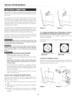
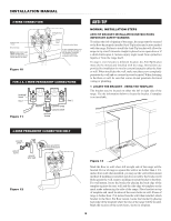
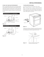
INSTALLATION MANUAL 3-WIRE CONNECTION Connect line 1 here. Ground strap Note: Install strain relief clamp. Center must always be attached to the center terminal on block. terminal block Connect line 2 here. Connect neutral here. A user supplied strain relief clamp must be installed at this location. It requires 1 3/8-inches (3.5 cm) diameter cord kit hole. Figure 10 FOR 3 & 4-WIRE PERMANENT CONNECTIONS terminal block line 1 terminal block line 1 neutral Figure 11 neutral grolinuend2strap ground strap ground plate groungdsrcopruleanwtde ground screw line 2 ANTI-TIP NORMAL INSTALLATION STEPS ANTI-TIP BRACKET INSTALLATION INSTRUCTIONS IMPORTANT SAFETY WARNING To reduce the risk of tipping of the range, the range must be secured to the floor by properly installed Anti-Tip bracket and screws packed with the range. Failure to install the Anti-Tip bracket will allow the range to tip over if excessive weight is placed on an open door or if a child climbs upon it. Serious injury might result from spilled hot liquids or from the range itself. If range is ever moved to a different location, the Anti-Tip bracket must also be moved and installed with the range. Instructions are provided for installation in wood or cement fastened to either the floor or wall. When installed to the wall, make sure that screws completely penetrate dry wall and are secured in wood or metal. When fastening to the floor or wall, be sure that screws do not penetrate electrical wiring or plumbing. 1 LOCATE THE BRACKET - USING THE TEMPLATE The bracket may be located on either the left or right side of the range. Use the information below to locate the bracket if template is not available. 4-WIRE PERMANENT CONNECTION ONLY ground plate ground screw ground plate ground screw ground wire lead proper ground for 4-wire permanent connection proper ground for wgirr4ceoo-ulwennaindrdeecptieornmanent Figure 12 Figure 13 Mark the floor or wall where left or right side of the range will be located. If rear of range is against the wall or no further than 1 1/4inches from wall when installed, you may use the wall or floor mount method. If molding is installed and does not allow the bracket to fit flush against the wall, remove molding or mount bracket to the floor. For wall mount, locate the bracket by placing the back edge of the template against the rear wall and the side edge of template on the mark made referencing the side of the range. Place bracket on top of template and mark location of the screw holes in wall. If rear of range is further than 1 1/4-inches from the wall when installed, attach bracket to the floor. For floor mount, locate the bracket by placing back edge of the template where the rear of the range will be located. Mark the location of the screw holes, shown in template. 6
-
 1
1 -
 2
2 -
 3
3 -
 4
4 -
 5
5 -
 6
6 -
 7
7 -
 8
8
 |
 |
