Sharp KB3300JK Service Manual - Page 21
Warning
 |
UPC - 074000612334
View all Sharp KB3300JK manuals
Add to My Manuals
Save this manual to your list of manuals |
Page 21 highlights
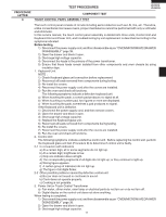
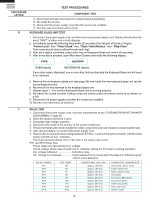
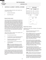
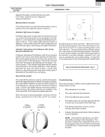
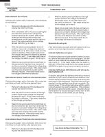
TEST PROCEDURES PROCEDURE LETTER COMPONENT TEST 8.Disconnect the power supply cord, and then remove covers. 9.Open the drawer and block it open. 10.Discharge high voltage capacitor. 11.Reconnect all leads removed from components during testing. 12.Re-install the covers. 13.Reconnect the power supply cord after the covers are installed. 14.Run the oven and check all function. KB-3300JS KB-3300JK KB-3300JW D DEFROST TEST WARNING : The oven should be fully assembled before following procedure. (1) Place one cup of water in the center of the tray in the oven cavity. (2) Close the drawer, touch the Defrost pad. Then select Steaks/Chops by touching the number pad 2. And touch the number pad 5. (Now, weight 0.5lb is set.) And then touch the start pad. (3) The oven is in Defrost cooking condition. (4) The oven will operate as follows WEIGHT 1ST STAGE 2ND STAGE 3RD. STAGE LEVEL TIME LEVEL TIME LEVEL TIME 0.5lb 60% 20sec. 40% 20sec. 30% 45sec. (5) If improper operation is indicated, the control unit is probably defective and should be checked. E PROCEDURES TO BE TAKEN WHEN THE FUSE ON THE PRINTED WIRING BOARD (PWB) IS OPEN. To protect the electronic circuits, this model is provided with a fuse added to the primary on the PWB. 1. Fuse check and repairs. 1) Disconnect the power supply cord. 2) Remove the covers. 3) Open the drawer and block it open. 4) Discharge high voltage capacitor. 5) If the Fuse is blown, replace power unit. 6) Make a visual inspection of the varistor. Check for burned damage. If the varistor has been burned, replace the power unit. 7) Examine the touch control transformer with a tester for the presence of layer short-circuit (check the primary coil resistance which is approximately 60Ω ± 10%). If any abnormal condition is detected, replace the touch control transformer. 8) Reconnect all leads removed from components during testing. 9) Re-install the covers. 10) Reconnect the power supply cord after the covers are installed. 11) Run the oven and check all functions. 2. Follow the troubleshooting guide given below, if indicator does not light up after above check and repairs are finished. 1) Disconnect the power supply cord. 2) Remove the covers. 3) Open the drawer and block it open. 4) Discharge high voltage capacitor. 5) Disconnect the leads to the primary of the power transformer. 6) Ensure that these leads remain isolated from other components and oven chassis by using insulation tape. 7) After that procedure, re-connect the power supply cord. 8) Follow the troubleshooting guide given below for repair. STEPS OCCURRENCE CAUSE OR CORRECTION 1 The rated AC voltage is not present between Check supply voltage and oven power cord. Pin Nos. 1and 3 of the 2-pin connecter (CN-B). 2 The rated AC voltage is present at primary Touch control transformer or secondary circuit defective. side of touch control transformer. Check and replace touch control transformer or power unit . 19
-
 1
1 -
2
-
3
-
4
-
5
-
6
-
7
-
8
-
9
-
10
-
11
-
12
-
13
-
14
-
15
-
 16
16 -
 17
17 -
 18
18 -
 19
19 -
 20
20 -
 21
21 -
 22
22 -
 23
23 -
 24
24 -
 25
25 -
 26
26 -
27
-
28
-
29
-
30
-
31
-
32
-
33
-
34
-
35
-
36
-
37
-
38
-
39
-
40
-
41
-
42
-
43
-
44
-
45
-
46
-
47
-
48
-
49
-
50
-
51
-
52
-
53
-
54
-
55
-
56
-
57
-
58
-
59
-
60
-
61
-
62
-
63
-
64
-
65
-
66
-
67
-
68
-
69
-
70
-
71
-
72
 |
 |