Sharp KB3300JK Service Manual - Page 43
Stop Switch, Secondary Interlock Switch And Monitor Switch Removal, Stop Switch, Secondary Interlock
 |
UPC - 074000612334
View all Sharp KB3300JK manuals
Add to My Manuals
Save this manual to your list of manuals |
Page 43 highlights
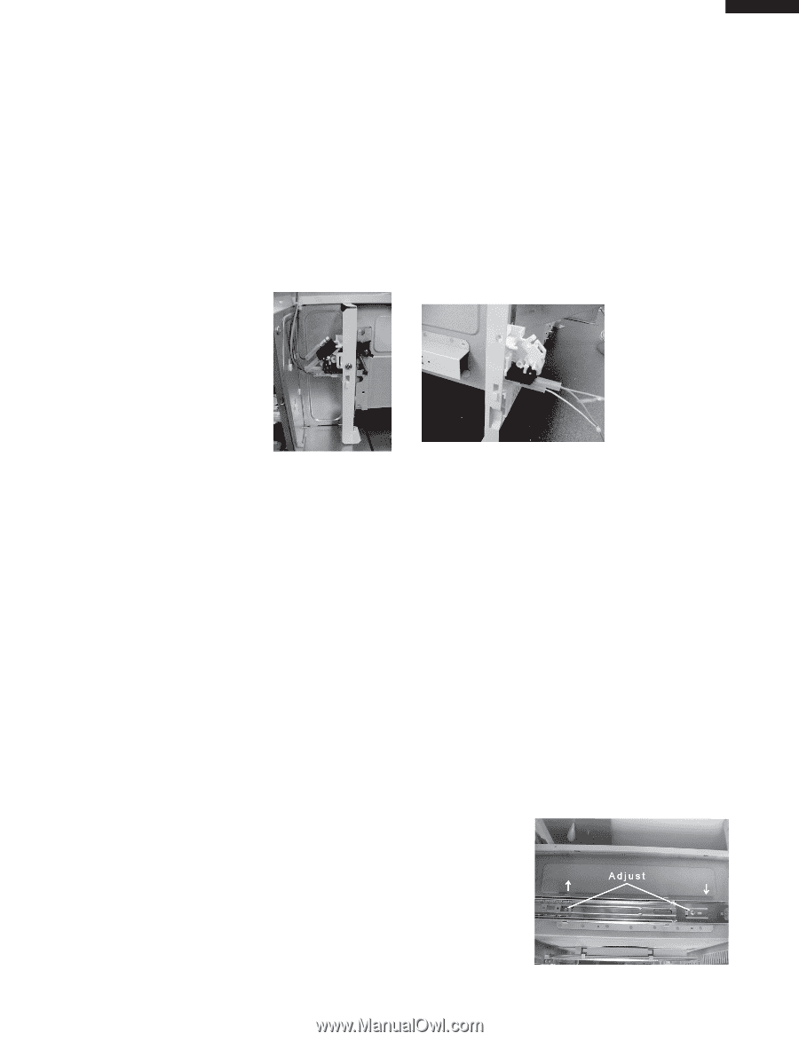
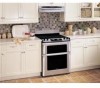
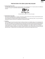
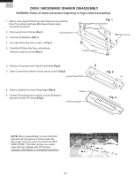
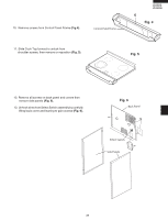
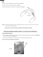
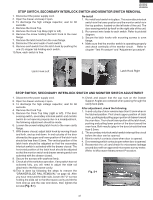
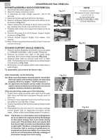
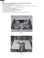
KB-3300JS KB-3300JK KB-3300JW STOP SWITCH, SECONDARY INTERLOCK SWITCH AND MONITOR SWITCH REMOVAL 1. Disconnect the power supply cord. 2. Open the drawer and keep it open. 3. To discharge the high voltage capacitor, wait for 60 seconds. 4. Remove the Cook Top. 5. Remove the Cook Top Stay (right or left). 6. Remove the screw holding the latch hook to the oven flange. 7. Remove the latch hook from the oven flange. 8. Disconnect the wire leads of each switch. 9. Remove each switch from the latch hook by pushing the one (1) stopper tab holding each switch. 10.Now, each switch is free. Re-install 1. Re-install each switch in its place. The secondary interlock switch is in the lower position and the monitor switch is in the top position, located on the left side of the unit. The door sensing switch by itself on the right side of the unit. 2. Re-connect wire leads to each switch. Refer to pictorial diagram. 3. Secure the latch hooks with mounting screws to oven flange. 4. Make sure that the monitor switch is operating properly and check continuity of the monitor circuit. Refer to chapter "Test Procedure" and "Adjustment procedure". Latch Hook Left Latch Hook Right STOP SWITCH, SECONDARY INTERLOCK SWITCH AND MONITOR SWITCH ADJUSTMENT 1. Disconnect the power supply cord. 2. Open the drawer and keep it open. 3. To discharge the high voltage capacitor, wait for 60 seconds. 4. Remove the Cook Top. 5. Remove the Cook Top Stay (right or left). If the door sensing switch, secondary interlock switch and monitor switch do not operate properly due to a misadjustment, the following adjustment should be made. 6. Loosen the screw holding latch hook to the oven cavity flange. 7. With drawer closed, adjust latch hook by moving it back and forth, and up and down. In and out play of the door allowed by the upper and lower position of the latch hook should be less than 0.5mm. The vertical position of the latch hook should be adjusted so that the secondary interlock switch is activated with the drawer closed. The horizontal position of the latch hook should be adjusted so that the monitor switch and drawer sensing switch are activated with the drawer closed. 8. Secure the screws with washers firmly. 9. Check all of the switches operation. If any switch has not activated fully, you will need to adjust the slide rail attached to the Microwave cavity. 10.This is done by following the steps to remove the "DRAWER/SLIDE RAIL REMOVAL" on page 42. After you have removed the slide rails, loosen the "2" screws holding the slide rail to the Microwave cavity and tilt the front end up and the rear end down, then tighten the screws (Fig. S-1). 11.Check and assure that the cap nuts on the Drawer Support Angles are centered when passing through the cavity face plate. After adjustment, check the following. 1. In and out play of door remains less than 0.5mm when in the latched position. First check upper position of latch hook, pushing and pulling upper portion of drawer toward the oven face. Then check lower portion of the latch hook, pushing and pulling lower portion of the door toward the oven face. Both results (play in the door) should be less than 0.5mm. 2. The secondary interlock switch switch interrupt the circuit before the door can be opened. 3. Monitor switch contacts close when door is opened. 4. Door sensing switch contacts open when door is opened. 5. Reassemble the unit and check for microwave leakage around door with an approved microwave survey meter. (Refer to Microwave Measurement Procedure. Fig. S-1 41
-
 1
1 -
2
-
3
-
4
-
5
-
6
-
7
-
8
-
9
-
10
-
11
-
12
-
13
-
14
-
15
-
16
-
17
-
18
-
19
-
20
-
21
-
22
-
23
-
24
-
25
-
26
-
27
-
28
-
29
-
30
-
31
-
32
-
33
-
34
-
35
-
36
-
37
-
 38
38 -
 39
39 -
 40
40 -
 41
41 -
 42
42 -
 43
43 -
 44
44 -
 45
45 -
 46
46 -
 47
47 -
 48
48 -
49
-
50
-
51
-
52
-
53
-
54
-
55
-
56
-
57
-
58
-
59
-
60
-
61
-
62
-
63
-
64
-
65
-
66
-
67
-
68
-
69
-
70
-
71
-
72
 |
 |