Sharp LC-32GP2U Service Manual
Sharp LC-32GP2U - AQUOS 32" Class 1080p Flat-Panel LCD HDTV Manual
 |
UPC - 074000370791
View all Sharp LC-32GP2U manuals
Add to My Manuals
Save this manual to your list of manuals |
Sharp LC-32GP2U manual content summary:
- Sharp LC-32GP2U | Service Manual - Page 1
LC-32GP2U SERVICE MANUAL No. S48I7LC32GP2U LCD COLOR TELEVISION MODEL LC-32GP2U In the interests of user-safety (Required by safety regulations in some countries) the set should be restored to its original condition and only parts identical to those specified should be used. OUTLINE This model - Sharp LC-32GP2U | Service Manual - Page 2
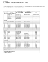
LC-32GP2U LOCU-32TGLP2IUNE AND DIFFERENCES FROM BASE MSOerDvEicLe Manual OUTLINE This model is based on the LC-32GP3U-B/W/R and is changed some parts. This Service Manual covers the modifications alone. For the other points, refer to the LC-32GP3U-B/W/R (No. S07U1LC32GP3U) Service Manual. LIST OF - Sharp LC-32GP2U | Service Manual - Page 3
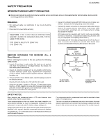
LSCA-32FGEP2TUY PRECAUTION Service Manual LC-32GP2U IMPORTANT SERVICE SAFETY PRECAUTION Service work should be performed only by qualified service technicians who are thoroughly familiar with all safety checks and the servicing guidelines which follow: „WARNING 1. For continued safety, no - Sharp LC-32GP2U | Service Manual - Page 4
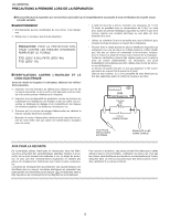
LC-32GP2U PRECAUTIONS A PRENDRE LORS DE LA REPARATION Ne peut effectuer la réparation qu' un technicien spécialisé qui s'est parfaitement accoutumé à toute vérification de sécurité et - Sharp LC-32GP2U | Service Manual - Page 5
PRECAUTIONS FOR USING LEAD-FREE SOLDER LC-32GP2U „Employing lead-free solder • "PWBs" of this model employs lead-free solder. The LF symbol indicates lead-free solder, and is attached on the PWBs and service manuals. The alphabetical character following LF shows the type of lead-free solder. - Sharp LC-32GP2U | Service Manual - Page 6
LC-32GP2U PRECAUTIONS IN SERVICING THE HDCP-KEY ROM Applied part: HDCP-KEY ROM IC8451 RH-IXC318WJQZY (updated ROM) The HDCP-KEY ROM shall be protected and managed for its information inside. In servicing this ROM, therefore, take the following information protection/management measures. 1) When - Sharp LC-32GP2U | Service Manual - Page 7
1. SPECIFICATIONS [1] SPECIFICATIONS Service Manual LC-32GP2U Item Model: LC-32GP2U LCD panel Resolution 32" screen size class Advanced Super View & BLACK TFT LCD (Diagonal Measurement : 31 /35 64 ") 2,073,600 pixels (1,920 1,080) TV-standard (CCIR) American TV Standard ATSC/NTSC - Sharp LC-32GP2U | Service Manual - Page 8
LC-32GP2U LCC-H32AGPP2UTER 2. OPERATION MANUAL [1] OPERATION MANUAL Part Names TV (Front) TV (Top/Side/Rear) Service Manual Remote control sensor OPC sensor OPC indicator SLEEP indicator POWER indicator Channel buttons (CH / ) MENU button Volume buttons (VOL / ) INPUT button POWER button AC - Sharp LC-32GP2U | Service Manual - Page 9
Part Names Remote Control Unit 1 17 2 3 18 4 19 5 6 20 7 21 8 9 22 10 23 11 24 25 12 26 27 13 14 28 29 15 16 30 When using the remote control unit, point it at the TV. LC-32GP2U 1 TV POWER: Switch the TV power on or enters standby. 2 DISPLAY: Display the channel - Sharp LC-32GP2U | Service Manual - Page 10
LC-32GP2U QUICK REFERENCE Detaching the Stand Before attaching (or detaching) the stand, unplug the AC cord from the AC INPUT terminal. CAUTION Do not remove the stand from the TV unless using an optional wall mount bracket to mount it. Before attaching/detaching the stand Before performing work - Sharp LC-32GP2U | Service Manual - Page 11
LC-32GP2U Appendix Troubleshooting Problem No power. Unit cannot be operated. Remote control unit does not operate. Picture is cut off/with sidebar screen. Strange color, light color, or color misalignment. Power is suddenly turned off. No picture. No sound. The TV sometimes makes a cracking sound - Sharp LC-32GP2U | Service Manual - Page 12
LC-32GP2U PC Compatibility Chart It is necessary to set the PC correctly to display XGA and WXGA signal. PC kHz SXGA+ 1400 x 1050 65.3 kHz UXGA 1600 x 1200 75.0 kHz *These 4 formats are not supported by the analog RGB terminal. Vertical Frequency 70 Hz 60 Hz 72 Hz 75 Hz 56 Hz 60 Hz 72 - Sharp LC-32GP2U | Service Manual - Page 13
Input Label Fine Sync. Position Language Reset Option Menu AQUOS LINK Setup Audio Only Digital Noise Reduction HDMI Setup Output Select Game Play Time Operation Lock Out Digital Setup Menu Software Update Some menu items may not be displayed depending on the selected input source. LC-32GP2U 2 - 6 - Sharp LC-32GP2U | Service Manual - Page 14
LC-32GP2U LCC-H32AGPP2UTER 3. DIMENSIONS [1] DIMENSIONS Service Manual Unit: inch (mm) 30 61/64 (786) 27 5/8 (701.4) 3 15/64 (82) 3 19/32 (91) 15 19/32 (395.9) 13 15/32 (342) 23 5/64 ( - Sharp LC-32GP2U | Service Manual - Page 15
OF MAJOR PARSTeSrvice Manual [1] REMOVING OF MAJOR PARTS 1. Remove the 3 Black Sheet. 2. Remove the 4 lock screws and detach the Stand. 3. Remove the 3 lock screws, 2 lock screws, 4 lock screws and detach the Rear Cabinet. 3 1 Black Sheet 3 Front Cabinet LC-32GP2U 3 2 Stand Rear Cabinet - Sharp LC-32GP2U | Service Manual - Page 16
LC-32GP2U 4. Disconnect the KM, VD, HM, US connectors from KEY Unit and SIDE Unit. 5. Remove the Top Cover Ass'y. 6. Remove the 2 lock screws and detach the SIDE Unit Ass'y. 7. Remove the 3 lock screws, 2 lock shaft and detach the Mini AV Shield. 8. Remove the 2 lock screws and detach the SIDE Unit - Sharp LC-32GP2U | Service Manual - Page 17
9. Remove the 10 lock screws, 2 lock screws, 4 lock shaft and detach the Main Shield. 10.Remove the 1 lock screw and detach the Stand Area Cover. 9 9 Main Shield 9 LC-32GP2U Stand Area Cover 10 4 - 3 - Sharp LC-32GP2U | Service Manual - Page 18
LC-32GP2U 11.Disconnect all the connectors from all the PWBs. 12.Remove the 2 lock screws and detach the Speaker (L)(R). 13.Remove the 1 lock screw and detach - Sharp LC-32GP2U | Service Manual - Page 19
14.Remove the 14 lock screws and detach the Tray Chassis. 15.Remove the 4 lock screws and detach the Stand Fix Angle. 14 Tray Chassis LC-32GP2U 15 Stand Fix Angle 4 - 5 - Sharp LC-32GP2U | Service Manual - Page 20
LC-32GP2U 16.Remove the 6 lock screws and detach the POWER Unit. 17.Remove the 4 lock screws and detach the TERMINAL Unit. 18.Remove the 1 lock screw, 2 - Sharp LC-32GP2U | Service Manual - Page 21
20.Remove the 4 lock screws and detach the LCD Shield Cover. 21.Remove the 4 lock screws and detach the LCD Panel Module. 21 LCD Shield Cover LC-32GP2U 20 21 4 - 7 - Sharp LC-32GP2U | Service Manual - Page 22
LC-32GP2U LCC-H32AGPP2UTER 5. ADJUSTMENT Service Manual [1] ADJUSTMENT PROCEDURE 1. Model number ID plug Model numbers are identified by inserting the destination ID plug (QCNCMA275WJQZ) in its specified slot of the destination ID connector SC9201/ SC9202 (QCNCWA715WJQZY). 㪋㪈 䇼㪢㪤䇽 㪐 - Sharp LC-32GP2U | Service Manual - Page 23
PartsGuide LC-32GP2U PARTS GUIDE No. S48I7LC32GP2U Note: The reference numbers on the PWB are arranged in alphabetical order. MODEL CONTENTS LC-32GP2U [1] PRINTED WIRING BOARD ASSEMBLIES [2] LCD PANEL (NOTE: THE PARTS HERE SHOWN ARE SUPPLIED AS AN ASSEMBLY BUT NOT INDEPENDENTLY.) [3] - Sharp LC-32GP2U | Service Manual - Page 24
LC-32GP2U NO. PARTS CODE PRICE NEW PART RANK MARK DELIVERY DESCRIPTION [1] PRINTED WIRING BOARD ASSEMBLIES N DUNTKE264FM02 N X MAIN Unit X TERMINAL Unit X SIDE Unit X POWER Unit [2] LCD PANEL (NOTE: THE PARTS HERE SHOWN ARE SUPPLIED AS AN ASSEMBLY BUT NOT INDEPEN- DENTLY.) N R1LK315D3LZ2BZ - Sharp LC-32GP2U | Service Manual - Page 25
[6] NOTE (Conductive cloth tape) Added parts ԘConductive Cloth Tape ˴Parts code: PSLDMB300WJQZ - Sharp LC-32GP2U | Service Manual - Page 26
LC-32GP2U [7] CABINET AND MECHANICAL PARTS 3 3-1 3-2 17 21 15 53 61 7 16 32 1-16 KEY Unit 1-1 1-8 18 45 1-12 1-13 1-7 1-16 1-6 1-9 1-7 42 46 18 1-12 1-13 1-12 1-8 1-6 1-2 1-13 1-11 54 25 9 - Sharp LC-32GP2U | Service Manual - Page 27
NO. PARTS CODE PRICE NEW PART RANK MARK DELIVERY DESCRIPTION [7] CABINET AND MECHANICAL PARTS 1 1-1 1-2 1-3 1-4 1-5 1-6 1-7 1-8 1-9 1-10 1-11 1-12 1-13 1-14 1-15 1-16 X Barrier Sheet J 32" LCD Panel Module Unit X Stand Area Cover X Model Label X Stand Fix Angle X Mini AV Angle X VESA Angle Up, - Sharp LC-32GP2U | Service Manual - Page 28
LC-32GP2U NO. PARTS CODE PRICE NEW PART RANK MARK DELIVERY [7] CABINET AND MECHANICAL PARTS 57 LANGKB249WJZZ AY 58 XBPSN50P16JS0 AB 59 PSLDMB300WJQZ AF 60 LHLDWA175WJUZ AC 61 LHLDWA176WJUZ AC 62 PSPAGA434WJZZ AB 63 XWHJZ32-05080 AB J Stand Fix Angle J Screw (for Stand Ass'y), x4 J - Sharp LC-32GP2U | Service Manual - Page 29
[9] PACKING PARTS (NOT REPLACEMENT ITEM) S6 S7 S5 S5 S4 S5 S3 S5 S5 S2 S1 7 LC-32GP2U S8 - Sharp LC-32GP2U | Service Manual - Page 30
LC-32GP2U NO. PARTS CODE PRICE NEW PART RANK MARK DELIVERY DESCRIPTION [9] PACKING PARTS ] SERVICE JIG (USE FOR SERVICING) Packing Case Stand Pad Wrapping Paper Wrapping Paper (Stand) Packing AV AP BA AP AV N AS N AX N BE J Connecting Cord (80pin 100cm) FFC, x2 LCD CONTROL to LCD - Sharp LC-32GP2U | Service Manual - Page 31
MEMO LC-32GP2U COPYRIGHT © XXXX BYSHARP CORPORATION ALL RIGHTS RESERVED. No part of this publication may be reproduced, stored in a retrieval system, or transmitted in any form or by any means, electronic, mechanical, photocopying, recording, or otherwise, - Sharp LC-32GP2U | Service Manual - Page 32
LC-32GP2U COPYRIGHT 2008 BY SHARP CORPORATION ALL RIGHTS RESERVED. No part of this publication may be reproduced, stored in a retrieval system, or transmitted in any form or by any means, electronic, mechanical, photocopying, recording, or otherwise,
-
 1
1 -
 2
2 -
 3
3 -
 4
4 -
 5
5 -
 6
6 -
 7
7 -
8
-
9
-
10
-
11
-
12
-
13
-
14
-
15
-
16
-
17
-
18
-
19
-
20
-
21
-
22
-
23
-
24
-
25
-
26
-
27
-
28
-
29
-
30
-
31
-
32
 |
 |
SERVICE MANUAL
Parts marked with "
" are important for maintaining the safety of the set. Be sure to replace these parts with specified ones for maintaining the
safety and performance of the set.
This document has been published to be used for
after sales service only.
The contents are subject to change without notice.
OUTLINE AND DIFFERENCES FROM BASE MODEL
OUTLINE
....................................................................
i
LIST OF CHANGED PARTS
......................................
i
SAFETY PRECAUTION
IMPORTANT SERVICE SAFETY
PRECAUTION
...........................................................
ii
PRECAUTIONS A PRENDRE LORS DE LA
REPARATION
...........................................................
iii
PRECAUTIONS FOR USING LEAD-FREE
SOLDER
..................................................................
iv
PRECAUTIONS IN SERVICING THE HDCP-
KEY ROM
..................................................................
v
CHAPTER 1. SPECIFICATIONS
[1]
SPECIFICATIONS
.................................................
1-1
CHAPTER 2. OPERATION MANUAL
[1]
OPERATION MANUAL
..........................................
2-1
CHAPTER 3. DIMENSIONS
[1]
DIMENSIONS
........................................................
3-1
CHAPTER 4. REMOVING OF MAJOR PARTS
[1]
REMOVING OF MAJOR PARTS
...........................
4-1
CHAPTER 5. ADJUSTMENT
[1]
ADJUSTMENT PROCEDURE
...............................
5-1
Parts Guide
TopPage
CONTENTS
In the interests of user-safety (Required by safety regulations in some countries) the set should
be restored to its original condition and only parts identical to those specified should be used
.
LCD COLOR TELEVISION
No. S48I7LC32GP2U
LC-32GP2U
LC-32GP2U
MODEL
OUTLINE
This model is based on the LC-32GP3U-B/W/R and is changed some parts. This Service Manual covers the mod-
ifications alone. For the other points, refer to the LC-32GP3U-B/W/R (No. S07U1LC32GP3U) Service Manual.