Sharp LC-32GP2U Service Manual - Page 8
Part Names - tv
 |
UPC - 074000370791
View all Sharp LC-32GP2U manuals
Add to My Manuals
Save this manual to your list of manuals |
Page 8 highlights
LC-32GP2U LCC-H32AGPP2UTER 2. OPERATION MANUAL [1] OPERATION MANUAL Part Names TV (Front) TV (Top/Side/Rear) Service Manual Remote control sensor OPC sensor OPC indicator SLEEP indicator POWER indicator Channel buttons (CH / ) MENU button Volume buttons (VOL / ) INPUT button POWER button AC INPUT terminal INPUT 5 terminal (HDMI) DIGITAL AUDIO OUTPUT terminal INPUT 7 terminals (PC-IN) INPUT 3 terminals INPUT 4 terminal (HDMI) SERVICE terminal RS-232C terminal INPUT 6 terminals (HDMI) Antenna/Cable in SUBWOOFER PRE OUT INPUT 2 terminals INPUT 1 terminals AUDIO OUTPUT terminals The illustrations in this operation manual are for explanation purposes and may vary slightly from the actual operations. 2 - 1
-
 1
1 -
2
-
 3
3 -
 4
4 -
 5
5 -
 6
6 -
 7
7 -
 8
8 -
 9
9 -
 10
10 -
 11
11 -
 12
12 -
 13
13 -
14
-
15
-
16
-
17
-
18
-
19
-
20
-
21
-
22
-
23
-
24
-
25
-
26
-
27
-
28
-
29
-
30
-
31
-
32
 |
 |

LC-32GP2U
2 – 1
LC-32GP2U
Service Manual
CHAPTER 2.
OPERATION MANUAL
[1] OPERATION MANUAL
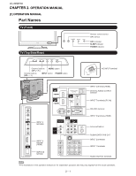
Part Names
TV (Front)
OPC
indicator
POWER
indicator
OPC sensor
Remote control sensor
SLEEP
indicator
TV (Top/Side/Rear)
The illustrations in this operation manual are for explanation purposes and may vary slightly from the actual operations.
RS-232C terminal
DIGITAL AUDIO OUTPUT
terminal
INPUT 5 terminal (HDMI)
INPUT 6 terminals (HDMI)
INPUT 7 terminals (PC-IN)
Antenna/Cable in
INPUT 1 terminals
AC INPUT terminal
INPUT 2 terminals
SUBWOOFER PRE OUT
AUDIO OUTPUT terminals
SERVICE
terminal
INPUT 3
terminals
INPUT 4
terminal
(HDMI)
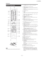
POWER
button
INPUT
button
MENU
button
Channel buttons
(
CH
/
)
Volume buttons
(
VOL
/
)