Sharp LC-32GP2U Service Manual - Page 16
Top Cover, Mini AV Angle, KEY Unit, SIDE Unit, Mini AV Key Cover, Mini AV Shield, Operation Button
 |
UPC - 074000370791
View all Sharp LC-32GP2U manuals
Add to My Manuals
Save this manual to your list of manuals |
Page 16 highlights
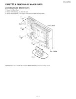
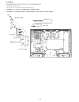
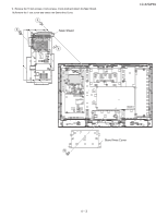
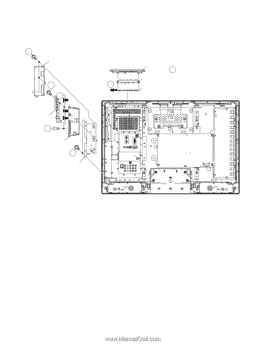
LC-32GP2U 4. Disconnect the KM, VD, HM, US connectors from KEY Unit and SIDE Unit. 5. Remove the Top Cover Ass'y. 6. Remove the 2 lock screws and detach the SIDE Unit Ass'y. 7. Remove the 3 lock screws, 2 lock shaft and detach the Mini AV Shield. 8. Remove the 2 lock screws and detach the SIDE Unit and Mini AV Key Cover from the Mini AV Angle. 7 Mini AV Shield 8 4 KM 4 VD HM SIDE Unit US 7 Top Cover 5 Operation Button KEY Unit Mini AV Key Cover 6 Mini AV Angle 4 - 2
-
 1
1 -
2
-
3
-
4
-
5
-
6
-
7
-
8
-
9
-
10
-
 11
11 -
 12
12 -
 13
13 -
 14
14 -
 15
15 -
 16
16 -
 17
17 -
 18
18 -
 19
19 -
 20
20 -
 21
21 -
22
-
23
-
24
-
25
-
26
-
27
-
28
-
29
-
30
-
31
-
32
 |
 |
LC-32GP2U
4 – 2
4.
Disconnect the KM, VD, HM, US connectors from KEY Unit and SIDE Unit.
5.
Remove the Top Cover Ass'y.
6.
Remove the 2 lock screws and detach the SIDE Unit Ass'y.
7.
Remove the 3 lock screws, 2 lock shaft and detach the Mini AV Shield.
8.
Remove the 2 lock screws and detach the SIDE Unit and Mini AV Key Cover from the Mini AV Angle.
7
6
5
7
8
Top Cover
Mini AV Angle
KEY Unit
SIDE Unit
Mini AV Key Cover
Mini AV Shield
Operation Button
4
4
VD
KM
HM
US