Sharp R-1505F Service Manual - Page 22
Qkitpb035, Control Unit And Key Unit Removal .
 |
View all Sharp R-1505F manuals
Add to My Manuals
Save this manual to your list of manuals |
Page 22 highlights
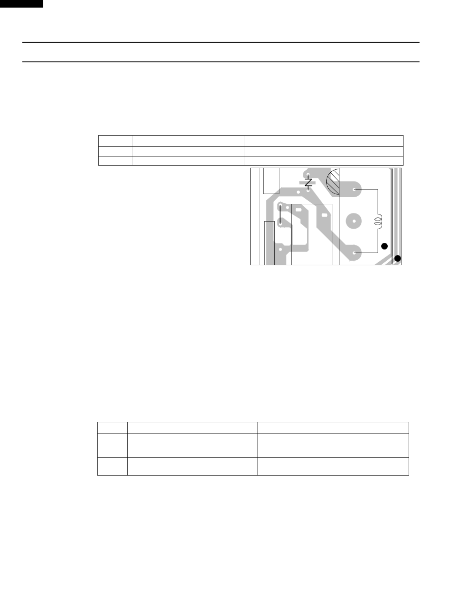
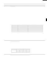
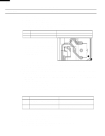
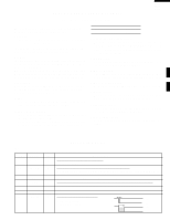
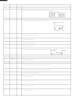
R-1500 R-1501 R-1505 R-1506 TEST PROCEDURES PROCEDURE LETTER COMPONENT TEST 1. Foil pattern check and repairs. 1) Disconnect the power supply cord. 2) Open the door and block it open. 3) To discharge high voltage capacitor, wait for 60 seconds. 4) Remove the control unit, referring to the procedure of " CONTROL PANEL ASSEMBLY, CONTROL UNIT AND KEY UNIT REMOVAL ". 5) Follow the troubleshooting guide given below for repair. STEPS 1 2 OCCURRENCE Only pattern at "a" is broken. Pattern at "a" and "b" are broken. 6) Make a visual inspection of the varistor. Check for burned damage and examine the transformer with a tester for the presence of layer short-circuit (check the primary coil resistance which is approximately 780Ω ± 10%). If any abnormal condition is detected, replace the defective parts. VRS1 CAUSE OR CORRECTION *Insert jumper wire J1 and solder. *Insert the coil RCILF2003YAZZ between "c" and "d". d c ba 1 S P RY2 J1 QKITPB035 T1 3 7) Reconnect all leads removed from components during testing. 8) Re-install the control unit to the control panel and re-install the control panel to the oven. 9) Reconnect the power supply cord. 10) Run the oven and check all functions. 2. Follow the troubleshooting guide given below, if indicator does not light up after above check and repairs are finished. 1) Disconnect the power supply cord, and then remove outer case. Refer to procedure of " HOOD EXHAUST LOUVER REMOVAL ", " REMOVAL OF OVEN FROM WALL " and " OUTER CASE REMOVAL ". 2) Open the door and block it open. 3) To discharge high voltage capacitor, wait for 60 seconds. 4) Remove the hood intake duct R. 5) Disconnect the leads to the primary of the power transformer. 6) Ensure that these leads remain isolated from other components and oven chassis by using insulation tape. 7) After that procedure, re-connect the power supply cord. 8) Follow the troubleshooting guide given below for repair. STEPS OCCURRENCE CAUSE OR CORRECTION The rated AC voltage is not present between 1 the normal open terminal of the relay RY2 and Check supply voltage and oven power cord. the normal open terminal of the relay RY1. 2 The rated AC voltage is present at primary side of low voltage transformer. Low voltage transformer or secondary circuit defective. Check and repair. 9) Disconnect the power supply cord. 10) Open the door and block it open. 11) To discharge high voltage capacitor, wait for 60 seconds. 12) Reconnect all leads removed from components during testing. 13) Re-install the hood intake duct R. 14) Re-install the outer case (cabinet). 15) Reconnect the power supply cord after the outer case is installed. 16) Run the oven and check all functions. 20
-
 1
1 -
2
-
3
-
4
-
5
-
6
-
7
-
8
-
9
-
10
-
11
-
12
-
13
-
14
-
15
-
16
-
 17
17 -
 18
18 -
 19
19 -
 20
20 -
 21
21 -
 22
22 -
 23
23 -
 24
24 -
 25
25 -
 26
26 -
 27
27 -
28
-
29
-
30
-
31
-
32
-
33
-
34
-
35
-
36
-
37
-
38
-
39
-
40
-
41
-
42
-
43
-
44
 |
 |