Sharp R-1505F Service Manual - Page 23
Touch Control Panel Assembly, Outline Of Touch Control Panel, Description Of Lsi
 |
View all Sharp R-1505F manuals
Add to My Manuals
Save this manual to your list of manuals |
Page 23 highlights
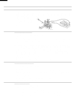
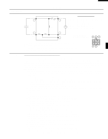
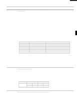
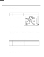
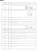
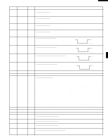
TOUCH CONTROL PANEL ASSEMBLY OUTLINE OF TOUCH CONTROL PANEL R-1500 R-1501 R-1505 R-1506 The touch control section consists of the following units as shown in the touch control panel circuit. (1) Key Unit (2) Control Unit (The Control unit consists of LSI Unit and Power U nit) The principal functions of these units and the signals communicated among them are explained below. Key Unit The key unit is composed of a matrix, signals generated in the LSI are sent to the key unit through P20, P21, P22, P23, P24, P25, P26 and P27. When a key pad is touched, a signal is completed through the key unit and passed back to the LSI through P43, P44, P45 and P46 to perform the function that was requested. Control Unit Control unit consists of LSI, power source circuit, synchronizing signal circuit, ACL circuit, buzzer circuit, relay circuit indicator circuit and back light circuit. 1) LSI This LSI controls the key strobe signal, relay driving signal for oven function and indicator signal. 2) Power Source Circuit This circuit generates voltages necessary for the control unit from the AC line voltage. In addition, the synchronizing signal is available in order to compose a basic standard time in the clock circuit. Symbol VC Voltage -5.3V Application LSI(IC1) 3) Synchronizing Signal Circuit The power source synchronizing signal is available in order to compose a basic standard time in the clock circuit. It incorporates a very small error because it works on commercial frequency. 4) ACL Circuit A circuit to generate a signals which resetting the LSI to the initial state when power is applied. 5) Buzzer Circuit The buzzer is responds to signals from the LSI to emit audible sounds (key touch sound and completion sound). 6) Door Sensing Switch A switch to inform the LSI if the door is open or closed. 7) Relay Circuit To drive the magnetron, fan motor, turntable motor, hood motor, and light the oven lamp and hood lamp. 8) Indicator Circuit This circuit consists of 22 segments and 3 common electrodes using a Light Crystal Display. 9) Back Light Circuit A circuit to drive the back light (Light emitting diodes LD1LD4). DESCRIPTION OF LSI LSI The I/O signal of the LSI is detailed in the following table. Pin No. Signal 1-2 VL2-VL1 3-6 AN7-AN4 7 AN3 8 AN2 9-10 11-13 14 AN1-AN0 P57-P55 CNTR0 I/O IN IN OUT IN OUT OUT OUT Description Power source voltage input terminal. Standard voltage for LCD. Terminal to change cooking input according to the Model. By using the A/D converter contained in the LSI, DC voltage in accordance with the Model in operation is applied to set up its cooking constant. Back light circuit (Light emitting diodes) driving signal. To input signal which communicates the door open/close information to LSI. Door close "H" level signal (0V). Door open "L" level signal (-5V). Terminal not used. Terminal not used. Signal to sound buzzer (2.0 kHz). A: key touch sound. B: Completion sound. 0.1 sec. A 2.0 sec. B H : GND L : -5V H : GND L : -5V 21
-
 1
1 -
2
-
3
-
4
-
5
-
6
-
7
-
8
-
9
-
10
-
11
-
12
-
13
-
14
-
15
-
16
-
17
-
 18
18 -
 19
19 -
 20
20 -
 21
21 -
 22
22 -
 23
23 -
 24
24 -
 25
25 -
 26
26 -
 27
27 -
 28
28 -
29
-
30
-
31
-
32
-
33
-
34
-
35
-
36
-
37
-
38
-
39
-
40
-
41
-
42
-
43
-
44
 |
 |
