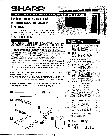
Sharp R-K4BW24 RK-46S24 , RK-46K24 , RK-46W24 Built-in Kit Instructions - Page 2
Cabinet, Opening, Exhaust, Assembly, Installation, Pokier, Supply
 |
View all Sharp R-K4BW24 manuals
Add to My Manuals
Save this manual to your list of manuals |
Page 2 highlights
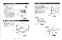
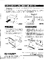
STEP 1 CABINET OR WALL OPENING The opening in the wall or cabinet must be within the following dimensions: HEIGHT : WIDTH OEPTH 15 11/16" to 16" 22 1/16" to 22 3/8" minimum 20 3/8" Outlet should NOT be in the shaded area as indicated on Sketch 1. NOTE 1: If the dimension of DEPTH (C) is more than 21", the outlet location may be any area on the rear wall. NOTE 2: The floor of the opening should be constructed of plywood strong enough to support the weight of the oven and floor load (about 100 pounds). The floor should be level for proper operation of the oven. Be sure to check the local building code as it may require that the opening be enclosed with sides, ceiling and rear partition. The proper functioning of the oven does not require the enclosure. STEP 2 EXHAUST DUCT ASSEMBLY INSTALLATION 1. Place the EXHAUST DUCT ASSEMBLY .in the opening. When the EXHAUST DUCT ASSEMBLY is in the opening correctly, its flanges will be tightly against the lower edge of the opening. See Sketch 2. 2. Secure the EXHAUST DUCT ASSEMBLY with two SCREWS B. See Sketch 2. 6" 4" 4 Sketch 1 SCREW B ••• EXHAUST DUCT ASSEMBLY SCREW B Sketch 2 STEP 3 POKIER SUPPLY CORD BOX ASSEMBLY AND REAR DUCT INSTALLATION 1. Roll the power supply cord into the REAR DUCT. , 2. Remove the screw 0 from left top of outer cabinet. Secure the left flange of the REAR DUCT with the screw 0 removed from the oven and secure the right flange of the REAR DUCT with SCREW A. See Sketch 3. 3. Plug the oven power supply cord into the POWER SUPPLY CORD BOX ASSEMBLY receptacle. See Sketch 4. 4. Slide the POWER SUPPLY CORD BOX ASSEMBLY into the REAR DUCT and secure the POWER SUPPLY CORD BOX ASSEMBLY and REAR DUCT with two SCREWS A. See Sketch 5. POWER SUPPLY CORD BOX ASSEMBLY REAR DUCT Sketch 3 I SCREW A 0 0 Sketch 4 POWER SUPPLY CORD BOX ASSEMBLY SCREW A SCREW A 0 REAR DUCT Sketch 5
-
 1
1 -
 2
2 -
 3
3
 |
 |
