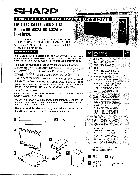
Sharp R-K4BW24 RK-46S24 , RK-46K24 , RK-46W24 Built-in Kit Instructions - Page 3
Frame, Installation, Louver
 |
View all Sharp R-K4BW24 manuals
Add to My Manuals
Save this manual to your list of manuals |
Page 3 highlights
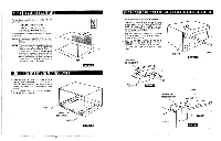
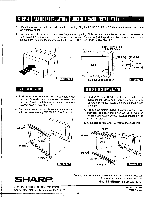
STEP 4 FRAME INSTALLATION LOUVER & SASH INSTALLATION 1. Place the oven adjacent to the wall or cabinet opening. Plug the POWER SUPPLY CORD BOX ASSEMBLY cord into the electrical outlet. , 2. Carefully guide the assembled oven into the prepared opening. Slide the oven on the EXHAUST DUCT ASSEMBLY. See Sketch 6. Avoid pinching the cord between the oven and the wall. Adjust the position of the oven so that the feet of the oven are fitted into the recesses of the EXHAUST DUCT ASSEMBLY. See Sketch 7. POWER SUPPLY CORD BOX ASSEMBLY OVEN REAR DUCT ASSEMBLY FOOT RECESS Sketch 6 EXHAUST DUCT ASSEMBLY Sketch 7 FRAME INSTALLATION 3. Position the FRAME ASSEMBLY to be square with the oven. Carefully place the FRAME ASSEMBLY on the oven. Check that it is level and then secure with two SCREWS C. See Sketch 8. 4. Secure the bottom portion of the FRAME ASSEMBLY with the two remaining SCREWS C. See Sketch 8. SCREW C SCREW C SCREW C SCREW C V r z Sketch 8 LOUVER & SASH INSTALLATION 3. Position the top LOUVER on the upper side of the oven so that it is level both horizontally and vertically. Secure with two SCREWS B provided in the kit. See Sketch 9. 4. Position the bottom LOUVER measuring the interval between the upper and lower LOUVERS with the SASH. Secure it with two SCREWS B provided in the kit. See Sketch 9. 5. Snap left and right SASHES into place. See Sketch 9. LOUVER SCREffi SCREW B SASH A il SCREW B LOUVER SASH SCREW B Sketch 9 SHARP SHARP ELECTRONICS CORPORATION Sharp Plaza, Mahwah, New Jersey 07430-2135 For any other assistance or information about this kit, please call Sharp's Customer Assistance Center at 1-800-BE-SHARP (1-800-237-4277) TINSEB325MRRO Printed in U.S.A. 4
-
 1
1 -
 2
2 -
 3
3
 |
 |
