Sharp VC-A410U Operation Manual - Page 3
Major, Components
 |
View all Sharp VC-A410U manuals
Add to My Manuals
Save this manual to your list of manuals |
Page 3 highlights
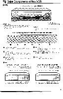
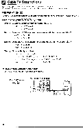
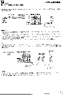
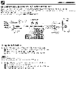
Major Components of Your VCR [Front] Cassette compartment (see Playback/Recording) SHARP (;) (VC-H820U) POWER button (When pressed to turn on the VCR, POWER LED indicator will light up. When the power is turned off, POWER LED indicator will turn off.) Basic function controls (see Playback/Recording) NOTE > • The design may be slightly different depending on the model. LED Indicator (explained throughout the operation instruction) 0 0 POWER LED indicator This indicator lights up whenever the VCR is turned on. TIMER LED indicator This indicator lights up when the VCR is set for timer recording, Simple Recording Timer and Recording with the Timer. 0 VCR LED indicator This indicator lights up when selecting "VCR" by using the TVNCR button. [Rear] (VC-H810U, VC-H811U, VC-H820U) Connection terminals (see Connecting the VCR and Cable TV Connections) Connection terminals (see Tape Dubbing) 6 0 REC LED indicator This indicator lights up during recording. This indicator flashes during REC-Pause. 0 TAMPER PROOF (0 ) LED indicator This indicator lights up when the set mode is locked. 0 Remote Sensor Point Remote Control at this window. (VC-A410U, VC-A411U, VC-A420U) Connection terminals (see Connecting the VCR and Cable TV Connections) Connection terminals (see Tape Dubbing) 3 4-> 4 OUTPUT CHANNEL selector (see Setting the 3 4 Output Channel Selector) 8 8 3 4-> 4 OUTPUT CHANNEL selector (see Setting the 3 4 Output Channel Selector) 7
-
 1
1 -
 2
2 -
 3
3 -
 4
4 -
 5
5 -
 6
6 -
 7
7 -
 8
8 -
 9
9 -
10
-
11
-
12
-
13
-
14
-
15
-
16
 |
 |
