Sharp XL-HP515 Service Manual - Page 64
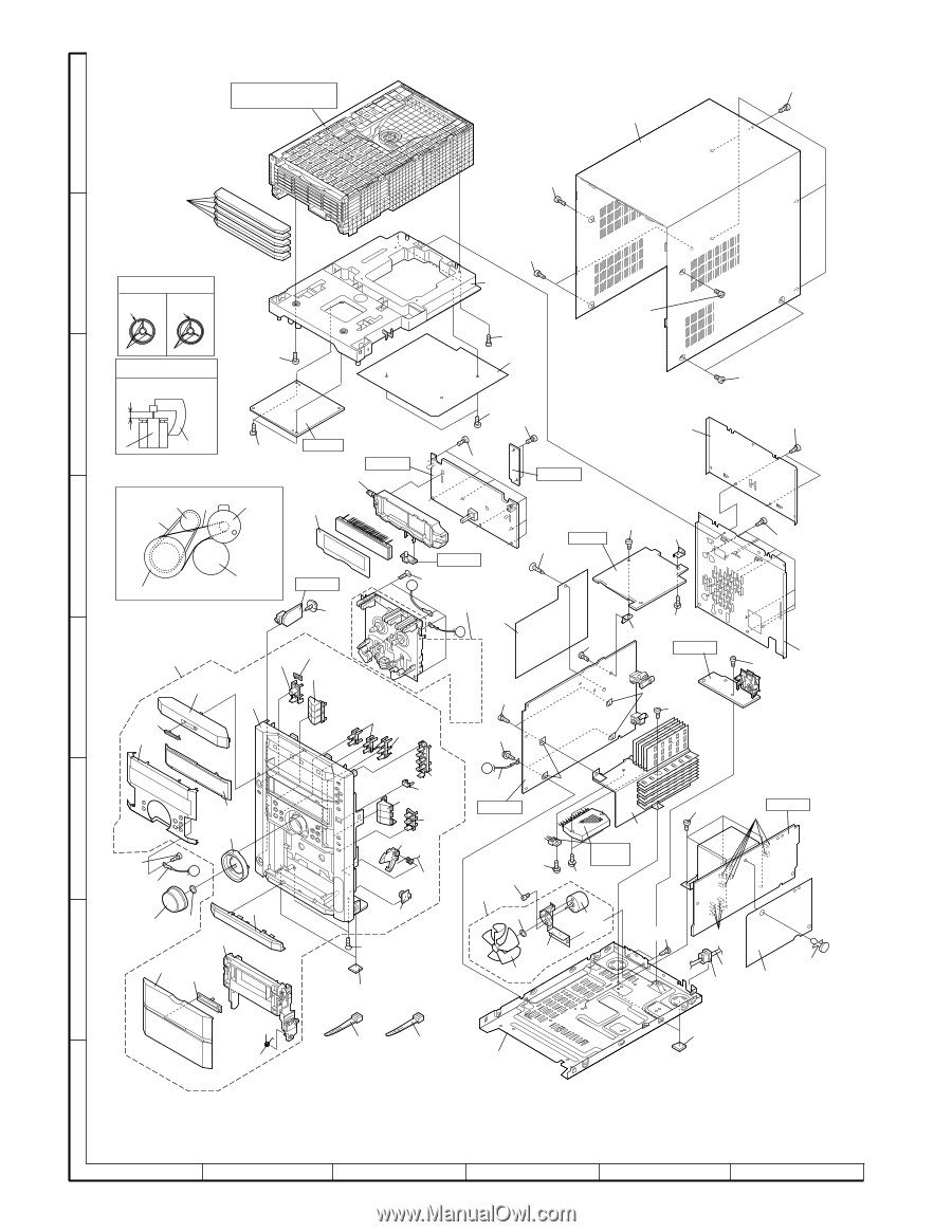
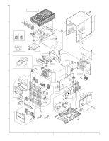
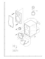
Cabinet Exploded View
 |
View all Sharp XL-HP515 manuals
Add to My Manuals
Save this manual to your list of manuals |
Page 64 highlights
XL-HP515 CD CHANGER MECHANISM UNIT A 205x5 204 610 614x5 B CAUTION : RING SPRING ASSY.INTO FAN POSITION. OK RING GAP NG RING GAP 614x2 218 610 FAN RIB FAN RIB CAUTION : MUST VISUAL CHECK AFTER FULLY INSERTED THE FAN TO MOTOR. ( FOR REFERENCE ONLY ) GAP IS 4.9 mm BETWEEN FAN AND FAN MOTOR BRACKET. C 610 4.9mm FAN BLADE FAN MOTOR BRACKET. 610x2 BELT CONNECTION PWB-D PWB-B1 219 610x2 223 610x2 609x2 609x6 PWB-B2 614x2 615x2 211 FF/REW Clutch Main Belt Motor 224 FF/REW Belt D PWB-B3 PWB-C 606 614 214 614x9 Flywheel Flywheel PWB-B4 B 611x4 603 213 226 A 201 201-13 201-2 201-17 213-1 213-2 213-3 213-4 E 201-4 201-1 213-5 213-6 616x2 213-7 201-8 201-18x2 213-8 201-12 201-19 602x2 614 214 614 PWB-A3 231x2 612 210 612 201-10 F 201-11 609 229 212 A 201-5 203 201-7 G 201-6 201-9 201-14 201-3 201-16 201-15 201-21 201-22 201-20 617x2 220x2 B 229 231x2 PWB-A1 ,y ,,yy,,yy,,yy 221 Silicon 604 608x2 Grease 605x2 202 202-4 202-3 (M971) 614x2 202-1 202-2 613x4 PWB-A2 230x6 230x4 228 216 225 607 201-23 232 215 217 220x2 H Note: Only the unit and consumable parts are supplied as parts supply for the Tape mechanism. 1 2 3 4 5 6 Figure 9 CABINET EXPLODED VIEW - 9 -
-
 1
1 -
2
-
3
-
4
-
5
-
6
-
7
-
8
-
9
-
10
-
11
-
12
-
13
-
14
-
15
-
16
-
17
-
18
-
19
-
20
-
21
-
22
-
23
-
24
-
25
-
26
-
27
-
28
-
29
-
30
-
31
-
32
-
33
-
34
-
35
-
36
-
37
-
38
-
39
-
40
-
41
-
42
-
43
-
44
-
45
-
46
-
47
-
48
-
49
-
50
-
51
-
52
-
53
-
54
-
55
-
56
-
57
-
58
-
 59
59 -
 60
60 -
 61
61 -
 62
62 -
 63
63 -
 64
64 -
 65
65 -
 66
66 -
 67
67 -
 68
68
 |
 |