Sony CPD-100ES Service Manual
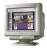
Sony CPD-100ES - 15" CRT Display Manual
 |
UPC - 027242533660
View all Sony CPD-100ES manuals
Add to My Manuals
Save this manual to your list of manuals |
Sony CPD-100ES manual content summary:
- Sony CPD-100ES | Service Manual - Page 1
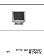
SERVICE MANUAL CPD-100ESCPD-100ES CPD-100ES Southern Hemisphere Model Equator Model Chassis No.SCC-L15B-A X2RCHASSIS Picture Tube Video image area Logical resolution Physical resolution SPECIFICATIONS 0.25 mm aperture grill pitch 15 notice. MICROFILM TRINITRON® COLOR COMPUTER DISPLAY - 1 - - Sony CPD-100ES | Service Manual - Page 2
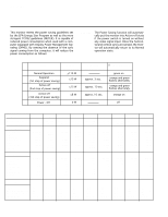
CPD-100ES POWER SAVING FUNCTION This monitor meets the power saving guidelines set by the EPA Energy Star Program as well as the more stringent TC092 guidelines (NUTEK). It is capable of reduced power consumption when used with a computer equipped with Display Resolution .836 63.981 15.630 3.778 0. - Sony CPD-100ES | Service Manual - Page 3
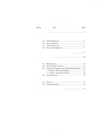
CPD-100ES TABLE OF CONTENTS Section Title Page 1. GENERAL 4 2. DISASSEMBLY 2-1. Cabinet Removal 7 2-2. Service Position 7 2-3. D Board Removal 7 2-4. Picture Tube Removal 8 3. SAFETY RELATED ADJUSTMENT 9 4. ADJUSTMENTS 10 5. DIAGRAMS 5-1. BlockDiagram 15 5-2. Circuit Boards Location - Sony CPD-100ES | Service Manual - Page 4
. For less common modes, the Multiscan 100ES/200ES's Digital Multiscan Technology will perform all of the complex adjustments necessary to ensure a high quality picture for any timing between 30 and 70␣ kHz. CPD-100ES/100EST and CPD-200ES/200EST No. Resolution Horizontal Vertical Graphics (dots - Sony CPD-100ES | Service Manual - Page 5
to reset, and then press the RESET button before the OSD (On Screen Display) disappears. To reset all adjustment data at once (for the received signal) " OSD automatically disappears 10 seconds after you release the buttons. To reset, press the RESET button while the OSD is on. CPD-100ES - 5 - 6 7 - Sony CPD-100ES | Service Manual - Page 6
CPD-100ES - 6 - Entering New Timings When using a video mode that is not one of the factory preset modes, some fine tuning may be required to optimize the display to your preferences. Simply adjust the monitor according to the preceding adjustment instructions. The adjustments will be stored - Sony CPD-100ES | Service Manual - Page 7
SECTION 2 DISASSEMBLY CPD-100ES 2-1. CABINET REMOVAL 3 Cabinet 2-2. SERVICE POSITION 2 Screw cover A board 2 Screw cover 1 3 1 Four screws (BVTP 4 x 16) D board 2 2-3. D BOARD REMOVAL 1 A board 6 Five screws (BVTP 3 x 12) 2 One screw (BVTT 4 x 8) 3 Cable stopper 4 Two screws ( - Sony CPD-100ES | Service Manual - Page 8
CPD-100ES 2-4. PICTURE TUBE REMOVAL 9 Demagnetization coil 10 Tension spring 2 A board 5 Neck assy 6 Deflection yoke 8 Picture tube 7 Four screws (Tapping screw 5) 1 Anode cap 3 Two screws (BVTP 4 x 16) - Sony CPD-100ES | Service Manual - Page 9
SECTION 3 SAFETY RELATED ADJUSTMENT CPD-100ES When replacing parts shown in the table below, the following operational checks must be performed as a safety precaution against X-rays emissions from the unit. D - BOARD - Sony CPD-100ES | Service Manual - Page 10
CPD-100ES SECTION 4 ADJUSTMENTS Connect the communication cable of the connector located on the D board on the monitor. Run the service software and then follow the instructions. IBM AT Computer as a Jig 1 1-690-391-21 2 A-1500-819-A Interface Unit 3 3-702-691-01 Connector Attachment To BUS - Sony CPD-100ES | Service Manual - Page 11
CPD-100ES 3. Receive White cross-hatch. 4. Adjust HMC and VMC at six-pole magnet. < 6 Pole Magnet> 2 1 G 2 G 1 5. Receive R.B. cross-hatch. 6. Adjust XBV at DY four-pole magnet. XBV - Sony CPD-100ES | Service Manual - Page 12
CPD-100ES 5-2. CIRCUIT BOARDS LOCATION A D 5-3. SCHEMATIC DIAGRAMS AND PRINTED WIRING BOARDS Note: • All capacitors are in µF unless otherwise noted. pF: µµF 50 WV or less are not indicated - Sony CPD-100ES | Service Manual - Page 13
- Sony CPD-100ES | Service Manual - Page 14
- Sony CPD-100ES | Service Manual - Page 15
MTZJ-T-77-18 RD4.7ES-T1B2 RD5.6ES-T1B2 1SS119-25TD CATHODE ANODE LM1281 28 15 EGP20DPKG23 EGP10GPKG23 1SS133T-77 CATHODE ANODE SN74HCT02AN 14 8 1 14 1 7 UF3ML-6505 RGP02-20EL-6394 3DL41A (LC6-15) HSS 82 CATHODE SNY425 24 ANODE 13 2SC5022-02 BC E TDA9105S 42 22 EGP30D 2SA1037K - Sony CPD-100ES | Service Manual - Page 16
CPD-100ES • Items with no part number and no description are not stocked because tRhEeF.yNOa. re PsAeRlTdNoOm. reqDuEiSrCeRdIPTfoIOrNroutine service. pout la securite. Ne les remplacer que par une piece portant le numero specifie. 16 33 15 32 14 7 34 4 6 35 5 13 7 10 12 11 22 21 89 20 - Sony CPD-100ES | Service Manual - Page 17
CPD-100ES 6-2. PACKING MATERIALS REF.NO. PART NO. DESCRIPTION REMARK 52 REF.NO. PART NO. DESCRIPTION 53 REMARK 51 54 55 56 REF.NO. PART NO. DESCRIPTION REMARK 51 3-860-654-01 52 * 4-060-187-01 53 ¡ 1-765-717-11 53 ¡ 1-558-481-11 MANUAL, INSTRUCTION CUSHION (TOP) ASSY. CORD SET, POWER (EQ) - Sony CPD-100ES | Service Manual - Page 18
7 ELECTRICAL PARTS LIST CPD-100ES A Note: RETF specifie. The components identified by [ in this manual have been carefully factory-selected for each RsEeMt iAnRoKrder " are not stocked since they are seldom required for routine service. Some delay should be anticipated when ordering these items. - Sony CPD-100ES | Service Manual - Page 19
CPD-100ES A Note: The components Identified by shading and mark ¡ are critical for safety. Replace only with part number specified. Note: Les composants identifies per un trame - Sony CPD-100ES | Service Manual - Page 20
composants identifies per un trame et une marque ¡ sont critiques pout la securite. Ne les remplacer que par une piece portant le numero specifie. CPD-100ES AD REF.NO. PART NO. DESCRIPTION REMARK REF.NO. PART NO. DESCRIPTION REMARK R019 1-216-025-91 METAL GLAZE 100 5% 1/10W R020 1-216-025 - Sony CPD-100ES | Service Manual - Page 21
CPD-100ES D Note: The components Identified by shading and mark ¡ are critical for safety. Replace only with part number specified. Note: Les composants identifies per un trame - Sony CPD-100ES | Service Manual - Page 22
securite. Ne les remplacer que par une piece portant le numero specifie. CPD-100ES D REF.NO. PART NO. DESCRIPTION C903 1-102-951-00 CERAMIC C904 D503 8-719-911-19 DIODE 1SS119-25 D504 8-719-051-97 DIODE 3DL41A(LC6-15) D505 8-719-110-17 DIODE RD10ESB2 D506 8-719-110-67 DIODE RD27ESB2 D508 8-719 - Sony CPD-100ES | Service Manual - Page 23
CPD-100ES D Note: The components Identified by shading and mark ¡ are critical for 59 IC MOC8105TV IC604 ¡ 8-759-072-98 IC TDA8138A IC652 ¡ 8-759-466-13 IC TL431ACLPRP IC801 ¡ 8-759-466-15 IC UPC6753 IC901 8-759-399-80 IC ST7272N5B1/CKO IC902 ¡ 8-759-269-04 IC SN74HCT02AN IC903 8-759-165-81 IC - Sony CPD-100ES | Service Manual - Page 24
identifies per un trame et une marque ¡ sont critiques pout la securite. Ne les remplacer que par une piece portant le numero specifie. CPD-100ES D REF.NO. PART NO. DESCRIPTION REMARK REF.NO. PART NO. DESCRIPTION REMARK Q502 ¡ Q503 Q504 Q505 Q507 8-729-043-37 TRANSISTOR IRFU214 8-729 - Sony CPD-100ES | Service Manual - Page 25
CPD-100ES D Note: The components Identified by shading and mark ¡ are critical for safety. Replace only with part number specified. Note: Les composants identifies per un trame - Sony CPD-100ES | Service Manual - Page 26
. Note: The components identified by [ in this manual have been carefully factory-selected for each set in order to satisfy regulations regarding X-ray radiation. Should replacement be required, replace only with the value originally used. CPD-100ES D REF.NO. PART NO. DESCRIPTION REMARK REF - Sony CPD-100ES | Service Manual - Page 27
CPD-100ES Note: The components Identified by shading and mark ¡ are critical for * 3-860-654-01 MANUAL, INSTRUCTION ¡ X-4033-083-1 TRANSFORMER ASSY, FLYBACK (NX-4130//J1E) 9-978-824-01 Sony Corporation Sony Technology Center, San Diego Product Quality Division Service Promotion Department - 40 -
-
 1
1 -
 2
2 -
 3
3 -
 4
4 -
 5
5 -
 6
6 -
 7
7 -
8
-
9
-
10
-
11
-
12
-
13
-
14
-
15
-
16
-
17
-
18
-
19
-
20
-
21
-
22
-
23
-
24
-
25
-
26
-
27
 |
 |
SPECIFICATIONS
MICROFILM
Picture Tube
Video image area
Logical resolution
Physical resolution
0.25 mm aperture grill pitch
15 inches measured diagonally
90-degree deflection
(14" maximum viewing image)
Approx. 284 x 212 mm (w/h)
(11
1/4
x 8
3/8
inches)
Horizontal: Max. 1280 dots
Vertical: Max. 1024 lines
Horizontal: Max. 1024 dots
Vertical: Max. 768 lines
Standard image area
Deflection frequency
AC input voltage / current
Dimensions
Mass
Approx. 270 x 202 mm (w/h)
(10
3/4
x 8 inches)
Horizontal: 30 to 70 KHz
Vertical: 50 to120 Hz
100 to 120 V, 50-60 Hz, 1.8 A
220 to 240 V, 50-60 Hz, 1.0 A
368 x 373 x 384.5 mm (w/h/d)
(14
1/2
x 14
3/4
x 15
1/4
inches)
Approx. 14.0kg (30 lb 14 oz)
Design and specifications are subject to change without notice.
SERVICE MANUAL
TRINITRON
®
COLOR
COMPUTER DISPLAY
X2R
CHASSIS
CPD-100ES
CPD-100ES
Southern Hemisphere Model
Equator Model
Chassis No.SCC-L15B-A