Sony DAV-LF1H Quick Start Guide - Page 1
Sony DAV-LF1H - Platinum Dvd Dream System Manual
 |
View all Sony DAV-LF1H manuals
Add to My Manuals
Save this manual to your list of manuals |
Page 1 highlights
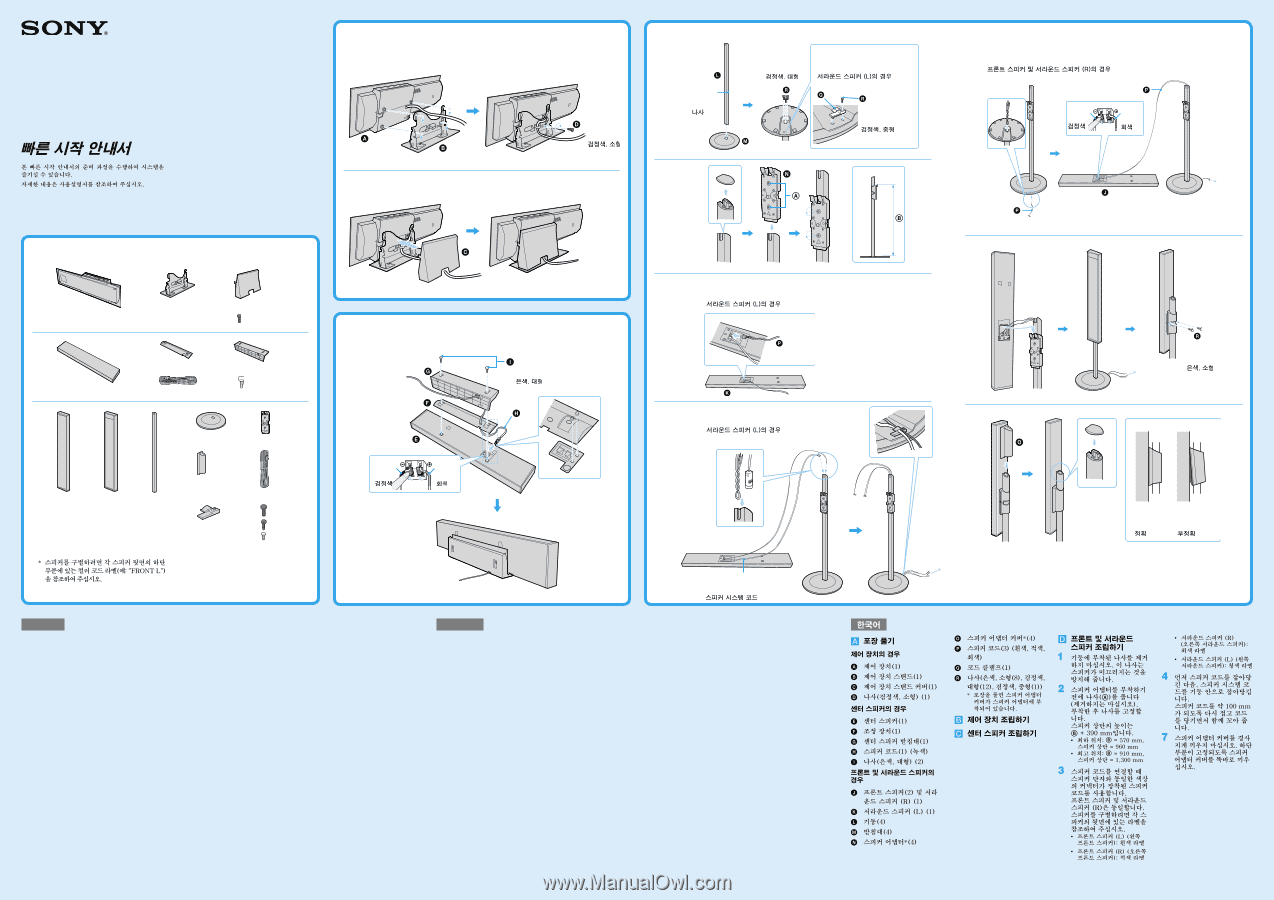
2-687-408-12(1) DAV-LF1H Quick Start Guide You can enjoy the system by performing the preparation in this Quick Start Guide. For details, refer to the operating instructions. Guide de démarrage Vous pouvez profiter rapidement de la chaîne en suivant la procédure de préparation décrite dans ce Guide de démarrage. Pour plus d'informations, reportez-vous au mode d'emploi. 1 2 © 2006 Sony Corporation Printed in Malaysia 1 * * Black, small Noire, petite 1 Screw Vis 2 Black, large Noire, grande For the surround speaker (L) Pour l'enceinte surround (L) Black, medium Noire, moyehhe Silver, large Argentée, grande 3 For the surround speaker (L) Pour l'enceinte surround (L) 4 For the surround speaker (L) Pour l'enceinte surround (L) * For discrimination between the speakers, see the color-coded label (ex. "FRONT L") at the lower part on the rear of each speaker. * Pour différencier les enceintes, consultez l'étiquette de couleur (ex. « FRONT L ») située à l'arrière, au bas de chaque enceinte. Black Noire Gray Gris Speaker system cord Cordon du système d'enceinte English Unpacking For the control unit Control unit (1) Control unit stand (1) Control unit stand cover (1) Screw (black, small) (1) For the center speaker Center speaker (1) Adjuster (1) Center speaker base (1) Speaker cord (1) (green) Screws (silver, large) (2) For the front and surround speakers Front speakers (2) and surround speaker (R) (1) Surround speaker (L) (1) Post (4) Base (4) Speaker adaptor* (4) Speaker adaptor cover* (4) Speaker cords (3) (white, red, gray) Cord clamp (1) Screws (silver, small (8), black, large (12), black, medium (1)) * When unpacking, the speaker adaptor cover is attached to the speaker adaptor. Assembling the control unit Assembling the center speaker Assembling the front and surround speakers 1 Do not remove the screw that is attached to the post. The screw is to prevent the speaker from slipping. 2 Loosen (but do not remove) the screws () before attaching the speaker adaptor. After attaching, secure the screws. The height of the speaker top is + 390 mm (15 3/8 inches). • Lowest position: = 570 mm (22 1/2 inches), Speaker top = 960 mm (37 7/8 inches) • Highest position: = 910 mm (35 7/8 inches), Speaker top = 1,300 mm (51 1/4 inches) 3 When connecting the speaker cord, use the speaker cord with the same color connector as the jack of the speaker. The front speakers and surround speaker (R) are identical. To discriminate between the speakers, see the label on the rear of each speaker. • Front speaker (L) (left front speaker): White label • Front speaker (R) (right front speaker): Red label • Surround speaker (R) (right surround speaker): Gray label • Surround speaker (L) (left surround speaker): Blue label 4 Draw the speaker cord first, then draw the speaker system cord into the post. Fold back the speaker cord about 100 mm (4 inches) and twist together when drawing the cords. 7 Do not insert the speaker adaptor cover at a slant. Insert the speaker adaptor cover straight down so that the lower part is fixed. Français Déballage Pour l'unité de commande Unité de commande (1) Support de l'unité de commande (1) Cache du support de l'unité de commande (1) Vis (noire, petite) (1) Pour l'enceinte centrale Enceinte centrale (1) Adaptateur (1) Base de l'enceinte centrale (1) Cordon d'enceinte (1) (vert) Vis (argentées, grandes) (2) Pour les enceintes avant et surround Enceintes avant (2) et enceinte surround (R) (1) Enceinte surround (L) (1) Montant (4) Base (4) Adaptateur pour enceinte* (4) Cache d'adaptateur pour enceinte* (4) Cordons d'enceinte (3) (blanc, rouge, gris) Attache-fils (1) Vis (argentée, petite (8), noire, grande (12), noire, moyenne (1)) * Au déballage, le cache d'adaptateur pour enceinte est fixé à l'adaptateur pour enceinte. Assemblage de l'unité de commande Assemblage de l'enceinte centrale Assemblage des enceintes avant et surround 1 Ne retirez pas la vis fixée au montant. Elle permet d'empêcher l'enceinte de glisser. 2 Desserrez les vis () (sans les retirer) avant de procéder à la fixation de l'adaptateur pour enceinte. Une fois qu'il est fixé, serrez les vis. La hauteur du dessus de l'enceinte est égale à + 390 mm (15 3/8 pouces). • Position la plus basse : = 570 mm (22 1/2 pouces), Dessus de l'enceinte = 960 mm (37 7/8 pouces) • Position la plus élevée : = 910 mm (35 7/8 pouces), Dessus de l'enceinte = 1 300 mm (51 1/4 pouces) 3 Lors du raccordement du cordon d'enceinte, choisissez celui qui possède le connecteur de même couleur que la prise de l'enceinte. Les enceintes avant et l'enceinte surround (R) sont identiques. Pour les distinguer, lisez l'étiquette située à l'arrière de chaque enceinte. • Enceinte avant (L) (enceinte avant gauche) : étiquette blanche • Enceinte avant (R) (enceinte avant droite) : étiquette rouge • Enceinte surround (R) (enceinte surround droite) : étiquette grise • Enceinte surround (L) (enceinte surround gauche) : étiquette bleue 4 Faites d'abord passer le cordon d'enceinte, puis le cordon du système d'enceinte dans le montant. Repliez le cordon d'enceinte sur 100 mm (4 pouces) environ et torsadez-le quand vous tirez les cordons. 7 N'insérez pas le cache d'adaptateur pour enceinte en l'inclinant. Insérez le cache d'adaptateur pour enceinte verticalement afin que sa partie inférieure soit fixe. 5 For the front speakers and surround speaker (R) Pour les enceintes avant et l'enceinte surround (R) Black Noire Gray Gris 6 Silver, small Argentée, petite 7 Correct Correct Incorrect Incorrect
-
 1
1 -
 2
2
 |
 |