Sony DVP-S360 Operating Instructions (CD/DVD Component) - Page 10
Receiver (Amplifier) Hookups, Required cords - dts
 |
View all Sony DVP-S360 manuals
Add to My Manuals
Save this manual to your list of manuals |
Page 10 highlights
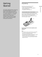
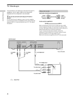
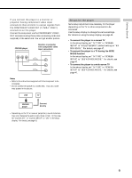
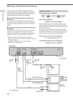
Receiver (Amplifier) Hookups Getting Started This connection is for listening to the sound through speakers connected to a receiver lacking a built-in DTS or Dolby* Digital decoder. Refer as wel to the instructions supplied with the component to be connectedl. z You can enjoy surround sounds even if you connect front speakers only You can use 3D sound imaging to create virtual rear speakers from the sound of the front speakers (L, R) without using actual rear speakers (VES:Virtual Enhanced Surround). For details, see page 33. z If you have a digital component with a built-in DTS or Dolby Digital decoder You can enjoy multi-channel surround sound by connecting the component via the DIGITAL OUT OPTICAL or COAXIAL connector using an optical or coaxial digital connecting cord (not supplied). For details on hookups and settings, see page 12. * Manufactured under license from Dolby Laboratories. "Dolby", "Pro Logic" and the double-D symbol are trademarks of Dolby Laboratories. Confidential unpublished works. ©1992-1997 Dolby Laboratories. All rights reserved. Required cords Audio connecting cord (not supplied) (1) White (L) Red (R) S video cord (not supplied) (1) White (L) Red (R) When connecting the cords, be sure to match the color-coded cord to the appropriate jacks on the components: Red (right) to Red and White (left) to White. Be sure to make connections firmly to avoid hum and noise. If you have a digital component such as a receiver (amplifier) with a digital connector, DAT or MD, connect the component via the DIGITAL OUT OPTICAL or COAXIAL connector using an optical or coaxial digital connecting cord (not supplied). Optical digital connecting cord (not supplied) (1) Coaxial digital connecting cord (not supplied) (1) CD/DVD player AUDIO OUT R L 1 DIGITAL OUT PCM/DTS/ DOLBY DIGITAL COAXIAL OPTICAL 2 VIDEO OUT S VIDEO OUT 1 1 2 2 COMPONENT VIDEO OUT Y PB/B-Y PR/R-Y To AUDIO OUT To DIGITAL OUT (COAXIAL) To DIGITAL OUT (OPTICAL) Take off the cap. To S VIDEO OUT To S VIDEO input INPUT VIDEO L AUDIO S VIDEO R or or : Signal flow 10 To optical digital input To coaxial digital input To audio input DIGITAL IN OPTICAL COAXIAL CD L R To an AC outlet TV Receiver (Amplifier) with a digital connector, MD deck, DAT deck, etc. Receiver (Amplifier)
-
 1
1 -
2
-
3
-
4
-
 5
5 -
 6
6 -
 7
7 -
 8
8 -
 9
9 -
 10
10 -
 11
11 -
 12
12 -
 13
13 -
 14
14 -
 15
15 -
16
-
17
-
18
-
19
-
20
-
21
-
22
-
23
-
24
-
25
-
26
-
27
-
28
-
29
-
30
-
31
-
32
-
33
-
34
-
35
-
36
-
37
-
38
-
39
-
40
-
41
-
42
-
43
-
44
-
45
-
46
-
47
-
48
-
49
-
50
-
51
-
52
-
53
-
54
-
55
-
56
-
57
-
58
-
59
-
60
-
61
-
62
-
63
-
64
-
65
-
66
-
67
-
68
 |
 |
