Sony DVWM2000P Product Manual (Operation Manual 1st Edition (Revised 6)) - Page 154
Maintenance Timings, for replacing components depends on the particular
 |
View all Sony DVWM2000P manuals
Add to My Manuals
Save this manual to your list of manuals |
Page 154 highlights
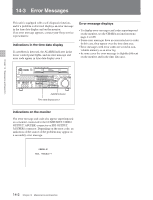
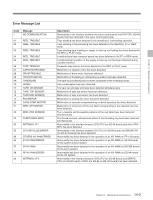
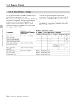
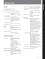
Chapter 14 Maintenance and Inspection 14-5 Regular Checks 14-5-2 Maintenance Timings Use the following table as a timing guide for checking and replacing components of the unit. These intervals are not guaranteed lifetimes; the timing for replacing components depends on the particular conditions of use. In particular, depending on the degree of dirt contamination and abrasion, pinch rollers and cleaners may require replacement earlier than suggested by this table. Note that an arrow in the table means that the component to be replaced is part of the assembly the arrow points to, which must be replaced as a whole. For information on severe conditions (frequent threading/ unthreading) or how to replace components, refer to the Maintenance Manual Volume 1. Component Digital hours meter Guideline replacement intervals indication (menu number in R: Replace C: Check, and replace if necessary parenthesis) 1000 hrs 2000 hrs 3000 hrs 4000 hrs 5000 hrs 6000 hrs Upper drum Drum running time (H02) C C C C(↓) Drum assembly C Brush slip ring assembly R R(↑) Video head cleaner (roller) R R Pinch roller assembly Tape running time (H03) R R Reel table assembly Pinch application assembly Tape running time (H03) R (Replace at interval of 4000 hours.) R Fan motor (card) Operation time (H01) Replace after 40,000 hours Fan motor (MD) Replace after 40,000 hours Power supply unit Replace after 40,000 hours 14-6 Chapter 14 Maintenance and Inspection
-
 1
1 -
2
-
3
-
4
-
5
-
6
-
7
-
8
-
9
-
10
-
11
-
12
-
13
-
14
-
15
-
16
-
17
-
18
-
19
-
20
-
21
-
22
-
23
-
24
-
25
-
26
-
27
-
28
-
29
-
30
-
31
-
32
-
33
-
34
-
35
-
36
-
37
-
38
-
39
-
40
-
41
-
42
-
43
-
44
-
45
-
46
-
47
-
48
-
49
-
50
-
51
-
52
-
53
-
54
-
55
-
56
-
57
-
58
-
59
-
60
-
61
-
62
-
63
-
64
-
65
-
66
-
67
-
68
-
69
-
70
-
71
-
72
-
73
-
74
-
75
-
76
-
77
-
78
-
79
-
80
-
81
-
82
-
83
-
84
-
85
-
86
-
87
-
88
-
89
-
90
-
91
-
92
-
93
-
94
-
95
-
96
-
97
-
98
-
99
-
100
-
101
-
102
-
103
-
104
-
105
-
106
-
107
-
108
-
109
-
110
-
111
-
112
-
113
-
114
-
115
-
116
-
117
-
118
-
119
-
120
-
121
-
122
-
123
-
124
-
125
-
126
-
127
-
128
-
129
-
130
-
131
-
132
-
133
-
134
-
135
-
136
-
137
-
138
-
139
-
140
-
141
-
142
-
143
-
144
-
145
-
146
-
147
-
148
-
 149
149 -
 150
150 -
 151
151 -
 152
152 -
 153
153 -
 154
154 -
 155
155 -
 156
156 -
 157
157 -
 158
158 -
 159
159 -
160
-
161
-
162
-
163
-
164
 |
 |