Sony FWD-32LX1 Protocol Manual - Page 10
Code Table1-a, IP Address, b]Range/Switch Code
 |
View all Sony FWD-32LX1 manuals
Add to My Manuals
Save this manual to your list of manuals |
Page 10 highlights
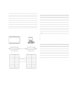
Code Table(1-a) [a]Function [b]Range/Switch Code Command Control Enquiry Standby Power On 0x35 PAP Input Detect (Left/Main) 0x20 INPUT1 DVI No Yes Disable Enable 0x36 PAP Input Detect (Right/Sub) 0x0A INPUT2 RGB No Yes Disable Enable 0x0B INPUT2 COMPONENT 0x0C OPTION1 VIDEO 0x0D OPTION1 S VIDEO 0x0E OPTION1 RGB 0x0F OPTION1 COMPONENT 0x10 OPTION2 VIDEO 0x11 OPTION2 S VIDEO 0x12 OPTION2 RGB 0x13 OPTION2 COMPONENT 0x20 INPUT1 DVI *1: Transmit the next command 10 seconds after Power On and Power Off commands are transmitted. If not, correct data may not be able to be acquired. *2: For INPUT SELECT, PAP, and Active Picture (SWAP), check the busy state using a Busy to INPUT command. *3: The Picture Position arrangement is as shown below. 12 34 IP Address Syntax Control Header 0x8C Category 0x00 Function 0x42 Data1 0x05 Data2 Data3 Data4 Address 0 Address 1 Address 2 0x00 - 0xFF 0x00 - 0xFF 0x00 - 0xFF Data5 Check Sum Address 3 0xXX 0x00 - 0xFF Answer Header Answer Check Sum Control 0x70 0x00 0x70 Completed 0x70 0x03 0x73 Command Canceled Example of IP Address setting 192.128.14.1 192 (0xC0) Address 0 128 (0x80) Address 1 14 (0x0E) Address 2 1 (0x01) Address 3 * IP Address command can be carried out even in the standby state. Code Table(1-a) [a]Function 0x42 IP Address 0x43 BackLight 0x44 Illumination 0x45 Control Mode 6 [b]Range/Switch code 0x00 - 0x64 0x00 OFF 0x01 Low 0x02 High 0x00 Main+Remocon 0x01 Main 0x02 Remocon Command Control Yes Yes Yes Yes Enquiry Yes Yes Yes Yes Standby Enable Disable Disable Disable Power On Enable Enable Enable Enable FWD-42LX1 FWD-32LX1
-
 1
1 -
2
-
3
-
4
-
 5
5 -
 6
6 -
 7
7 -
 8
8 -
 9
9 -
 10
10 -
 11
11 -
 12
12 -
 13
13 -
 14
14 -
 15
15 -
16
-
17
-
18
-
19
-
20
-
21
-
22
-
23
-
24
 |
 |
